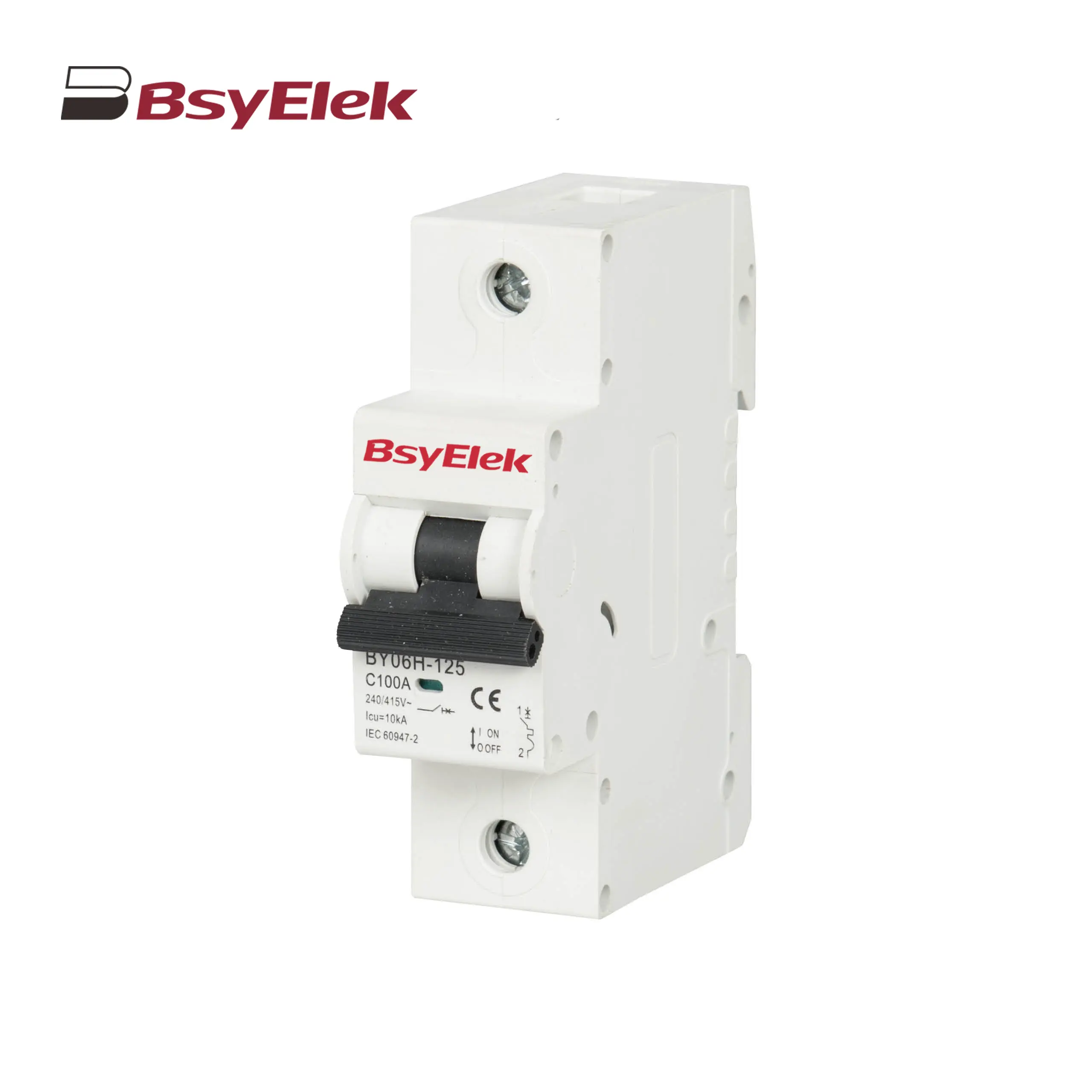
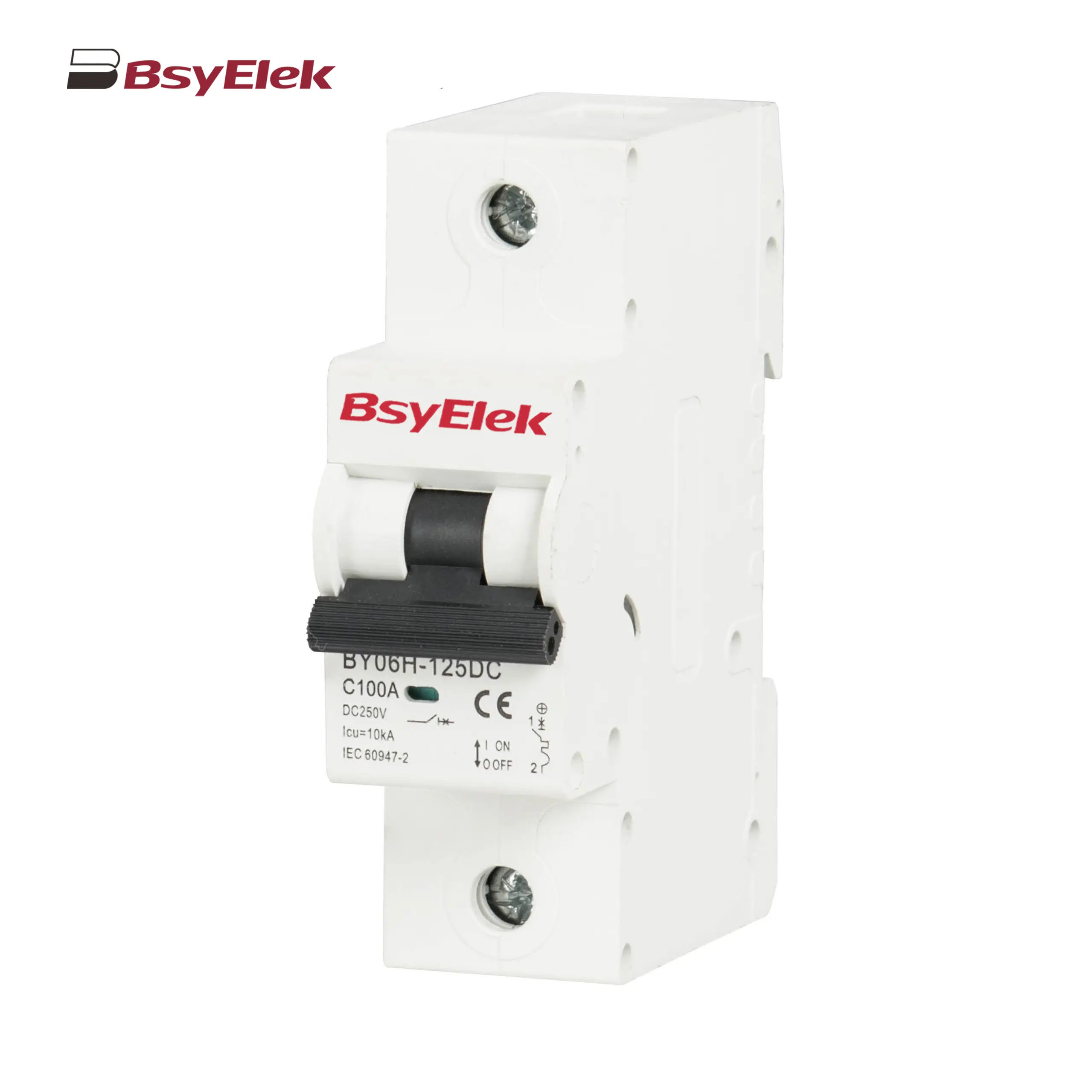
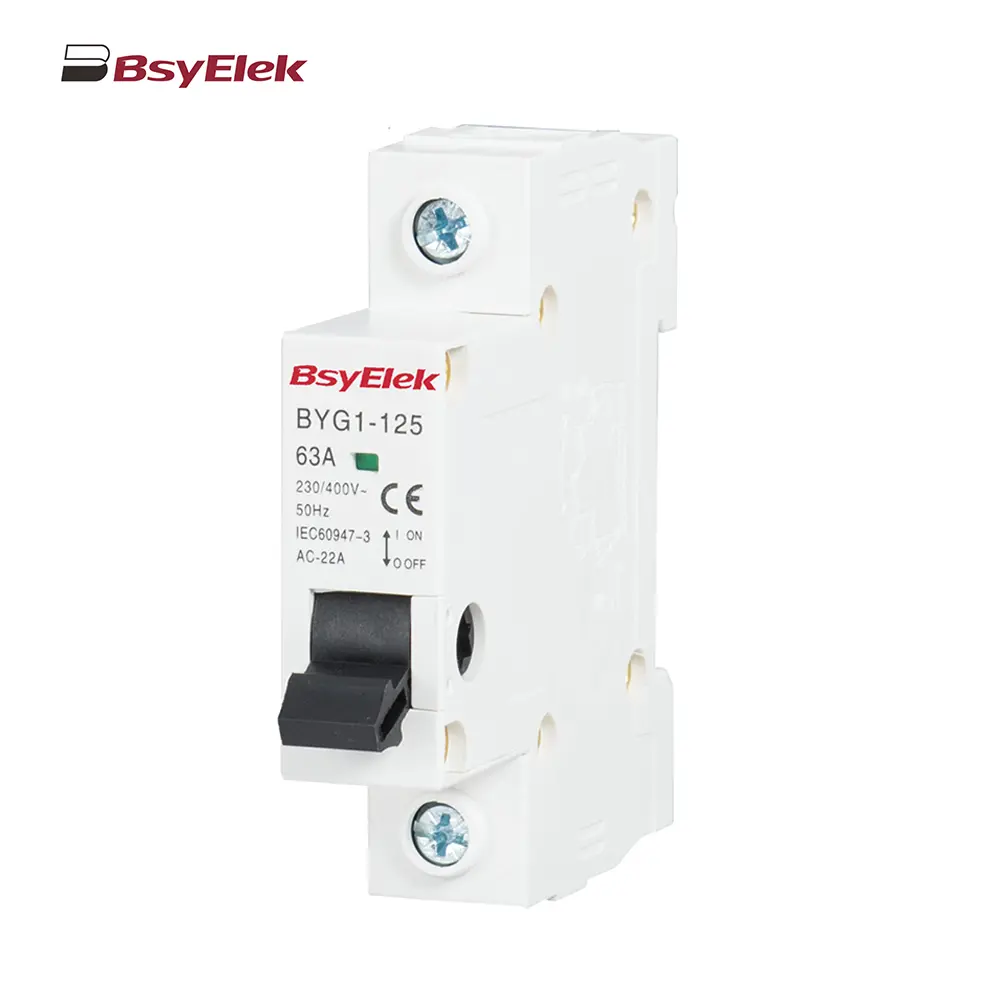
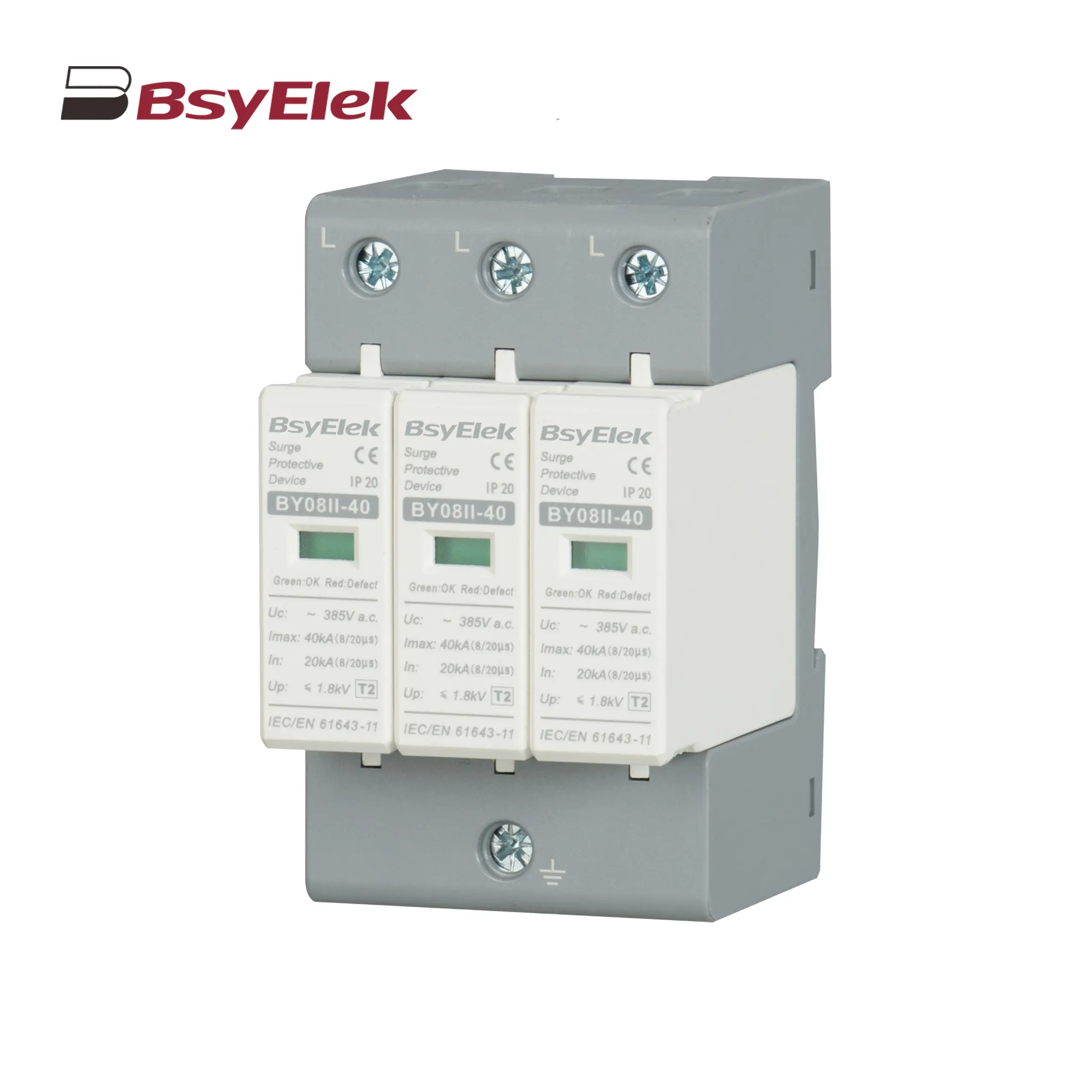
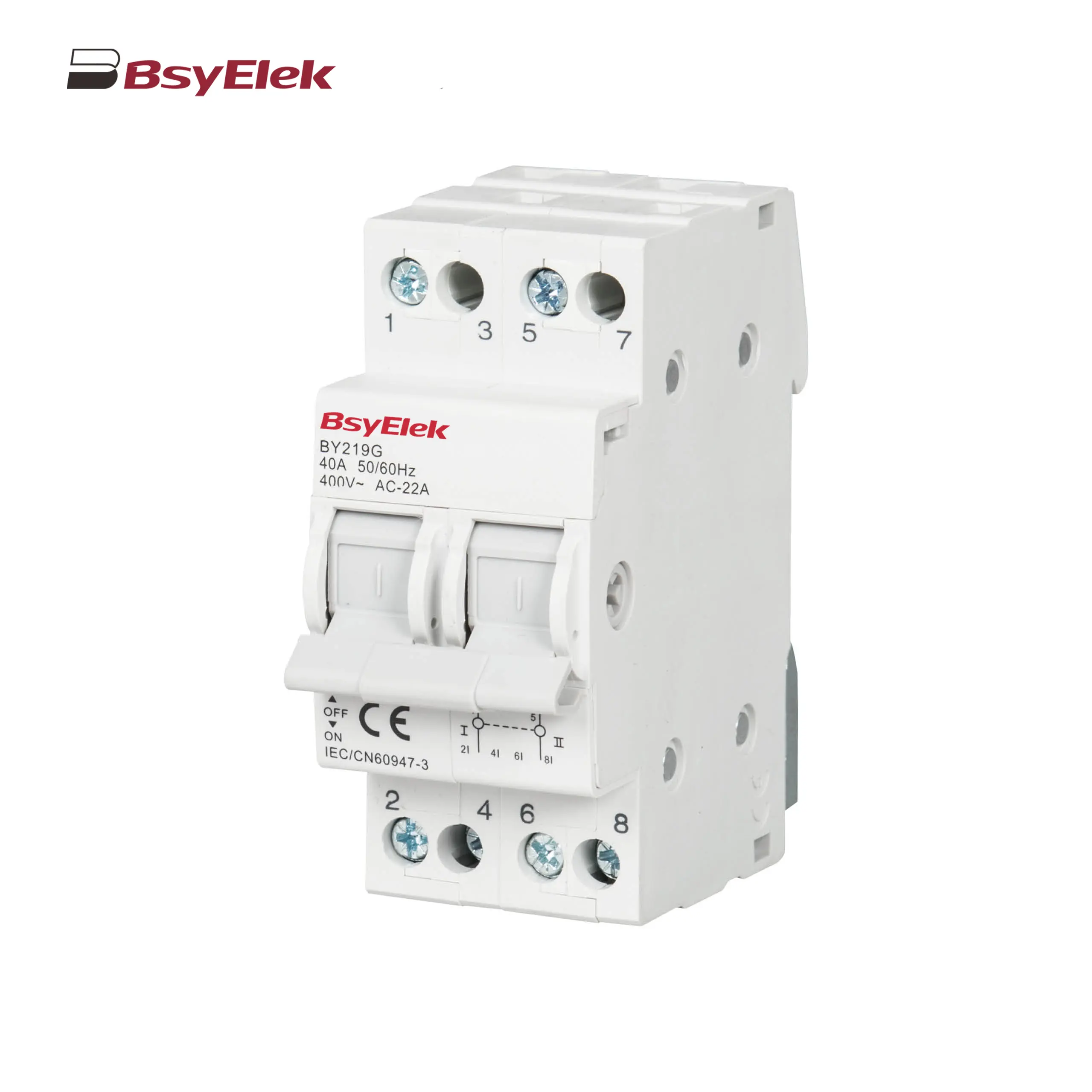
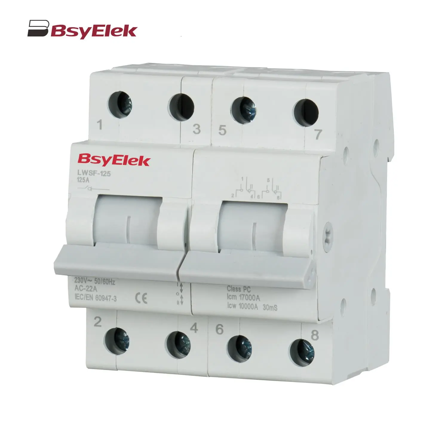
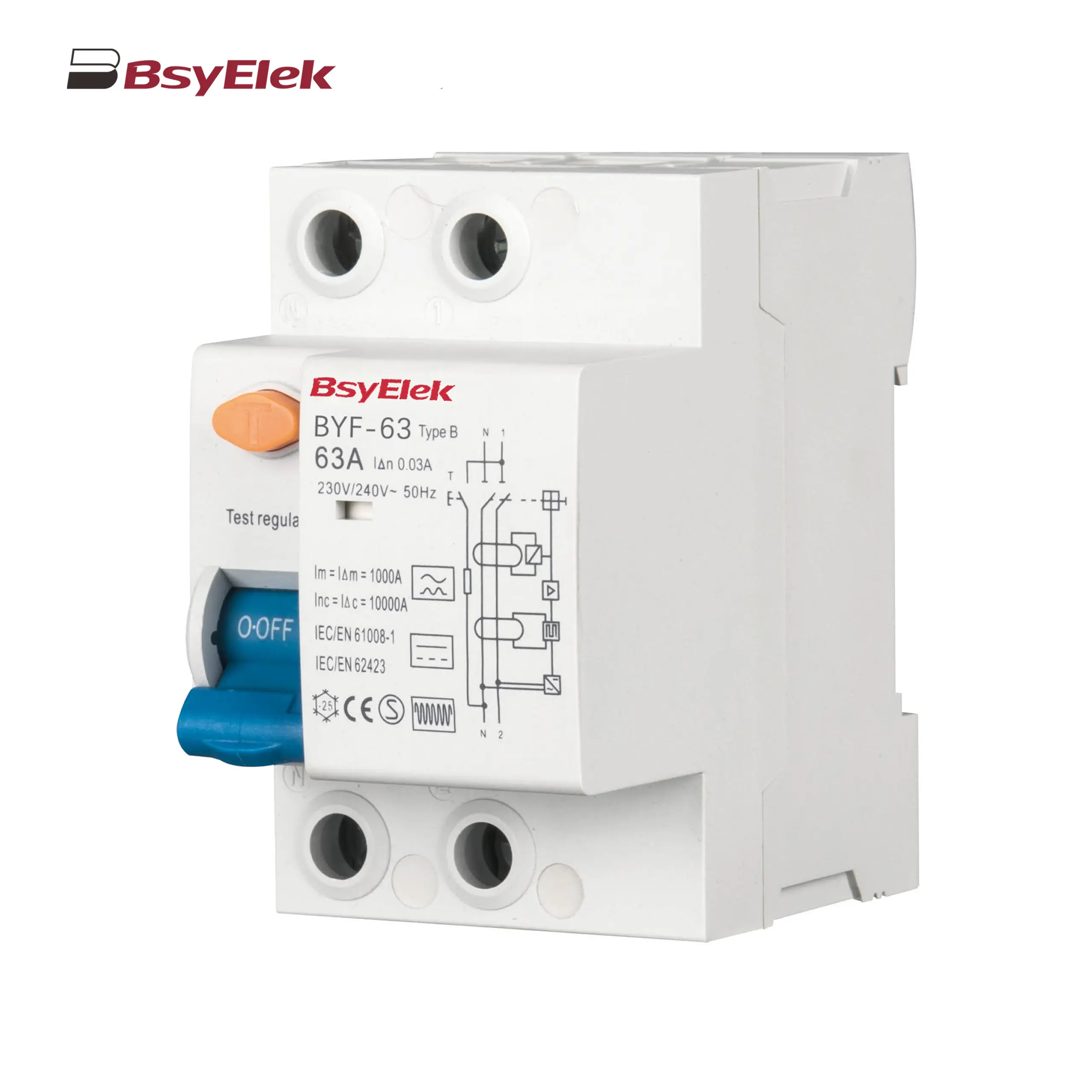
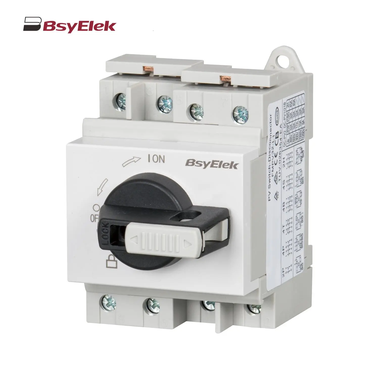
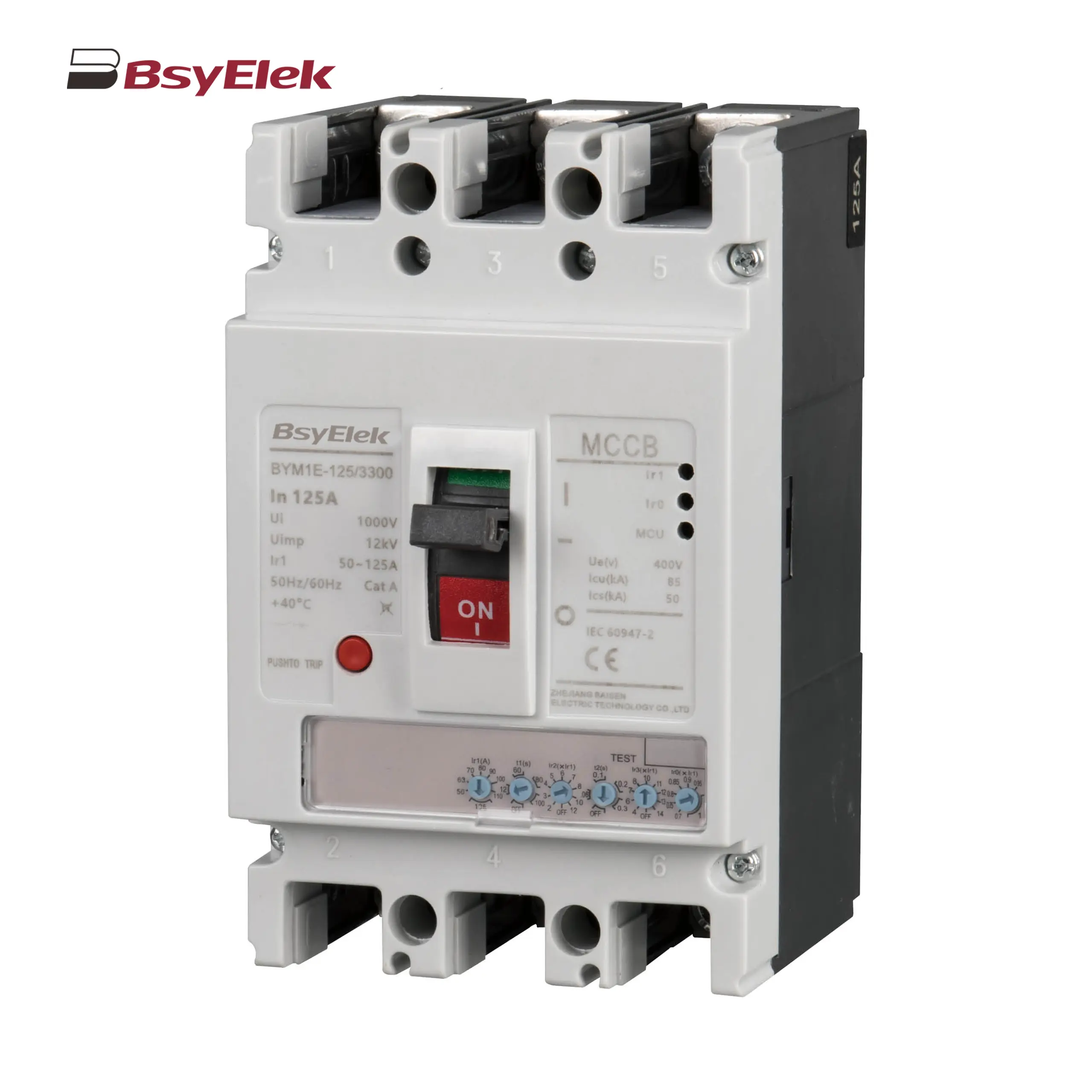
BY06H-125 MCB 10-15KA Miniature Circuit Breaker
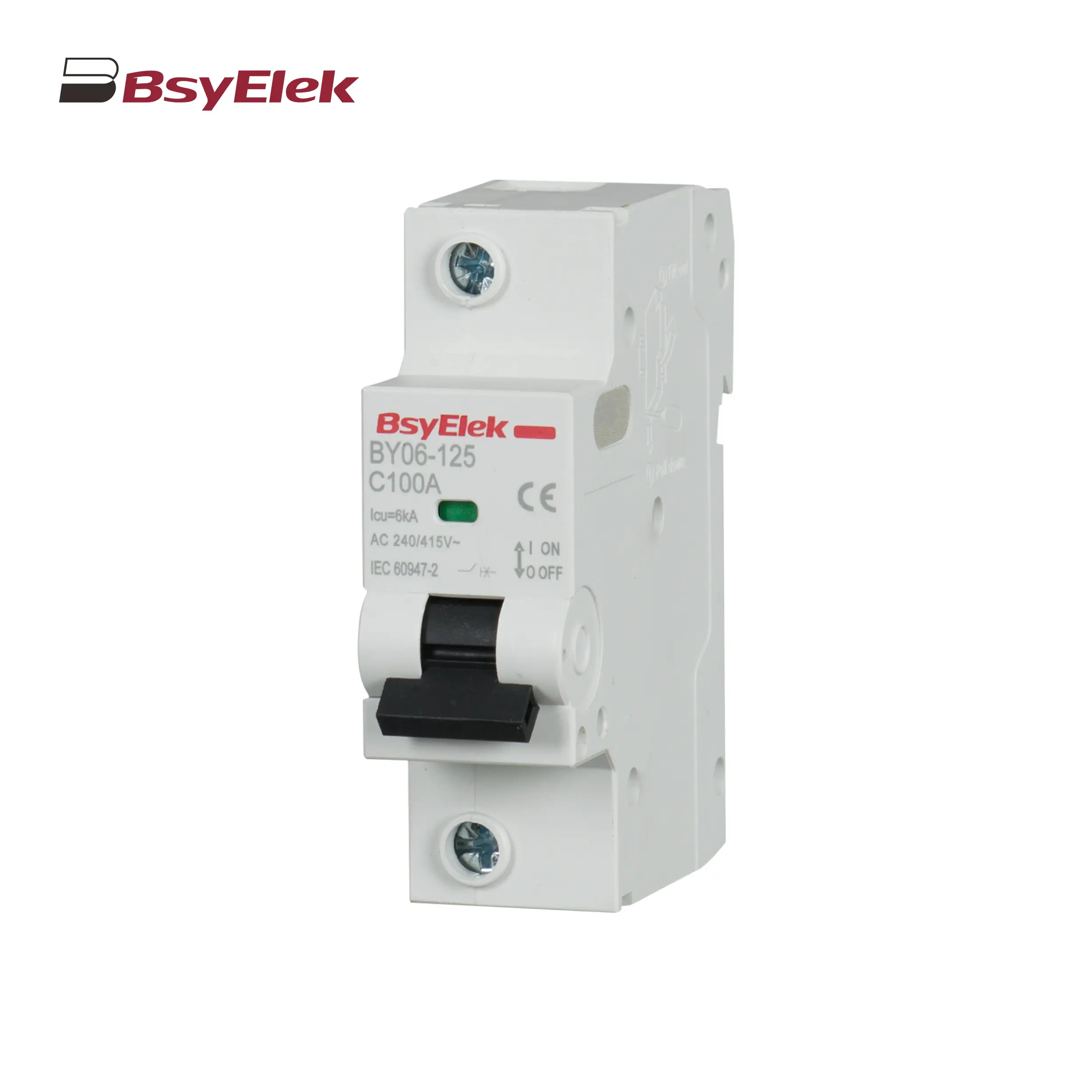
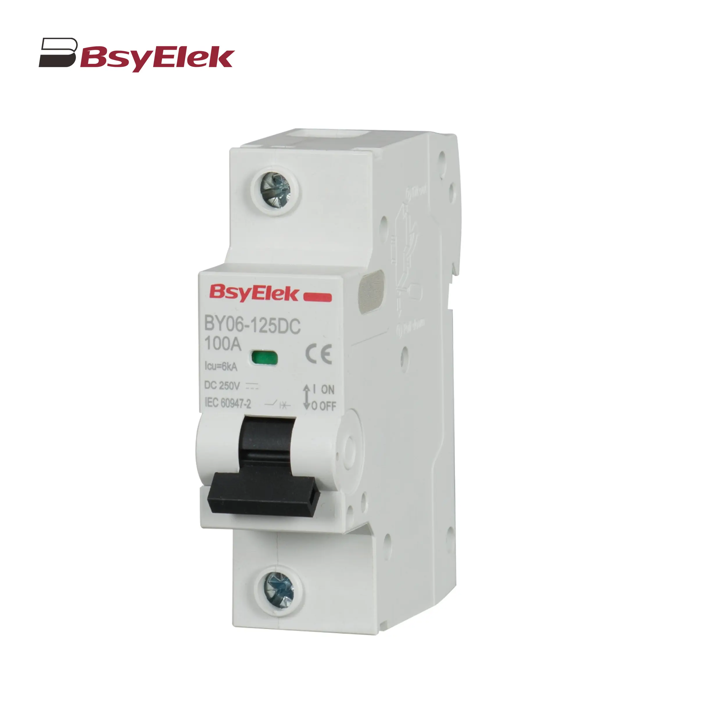
BY06-125 MCB 6KA Miniature Circuit Breaker
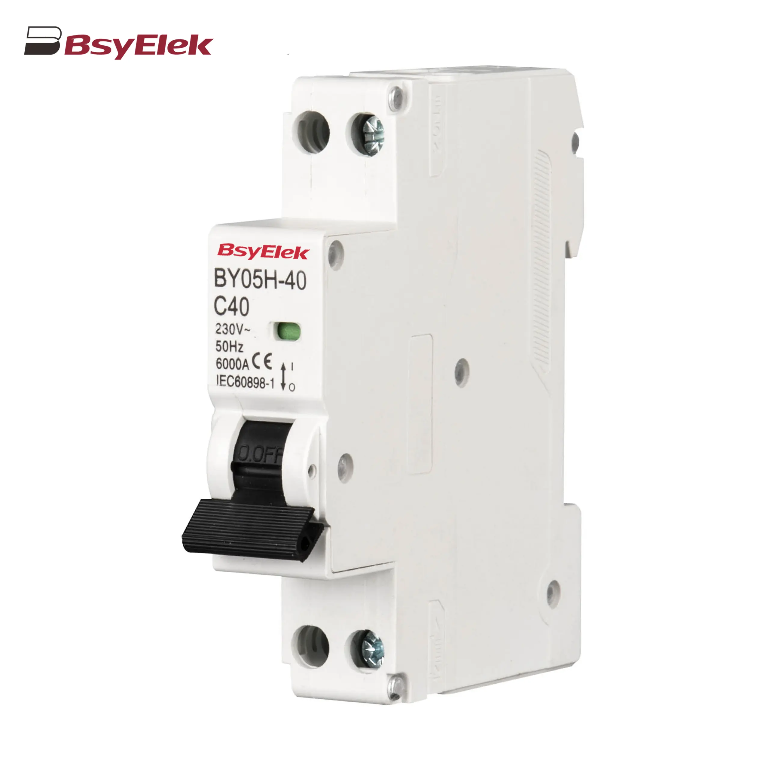
BY05H-40 MCB Single Modular 6KA Miniature Circuit Breaker
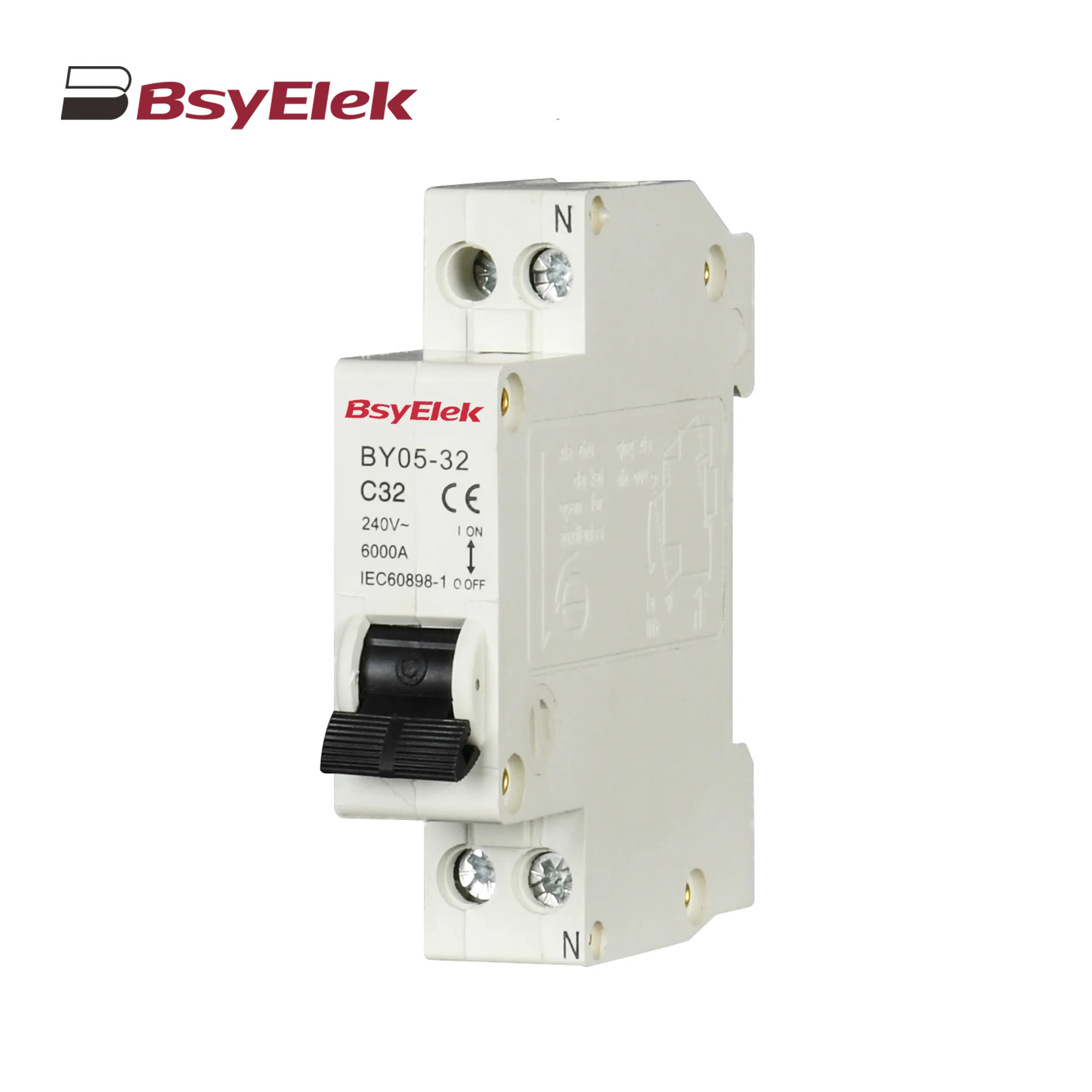
BY05-32 MCB Single Modular 3KA Miniature Circuit Breaker
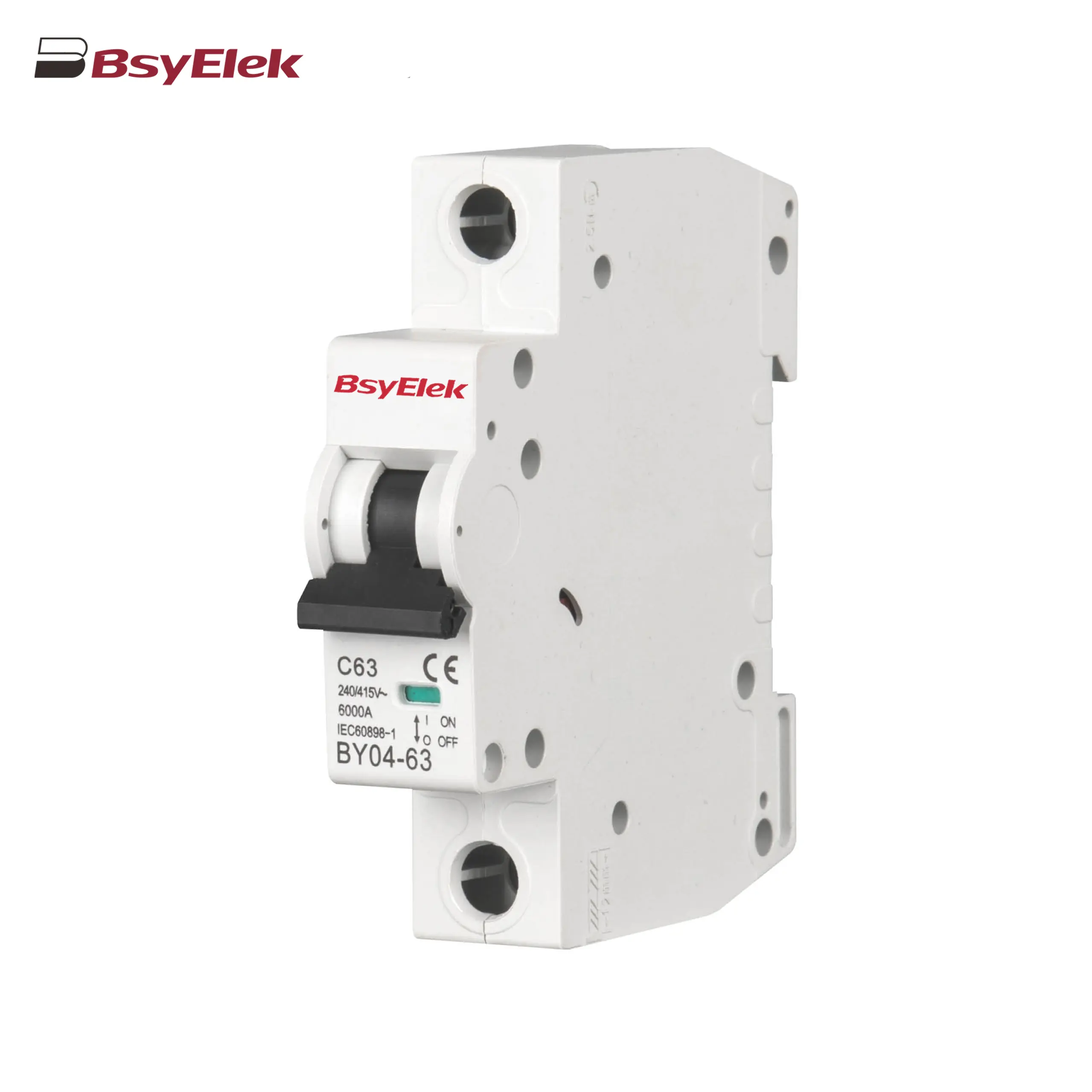
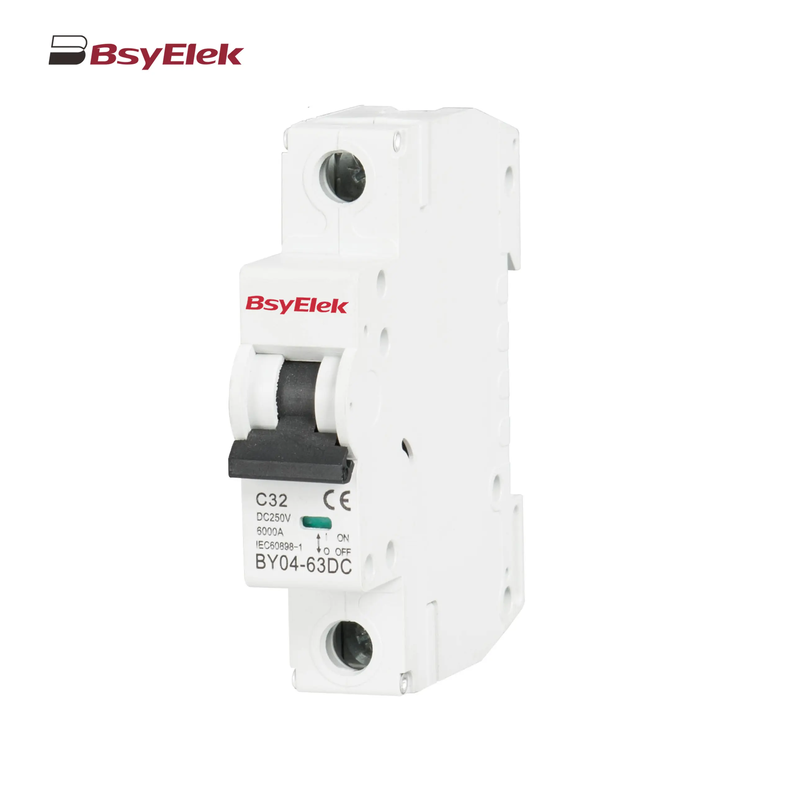
BY04-63 MCB 6-10KA Miniature Circuit Breaker
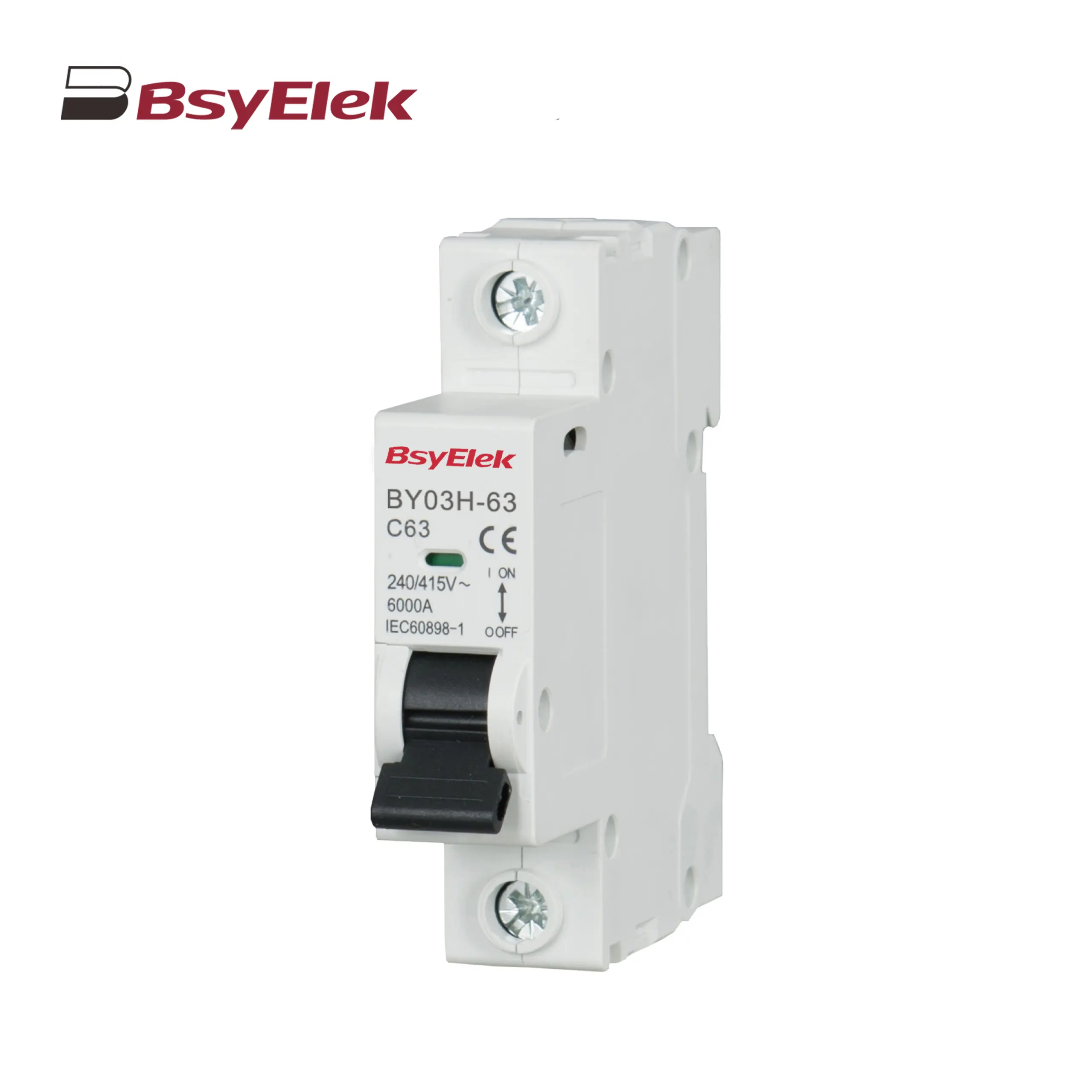
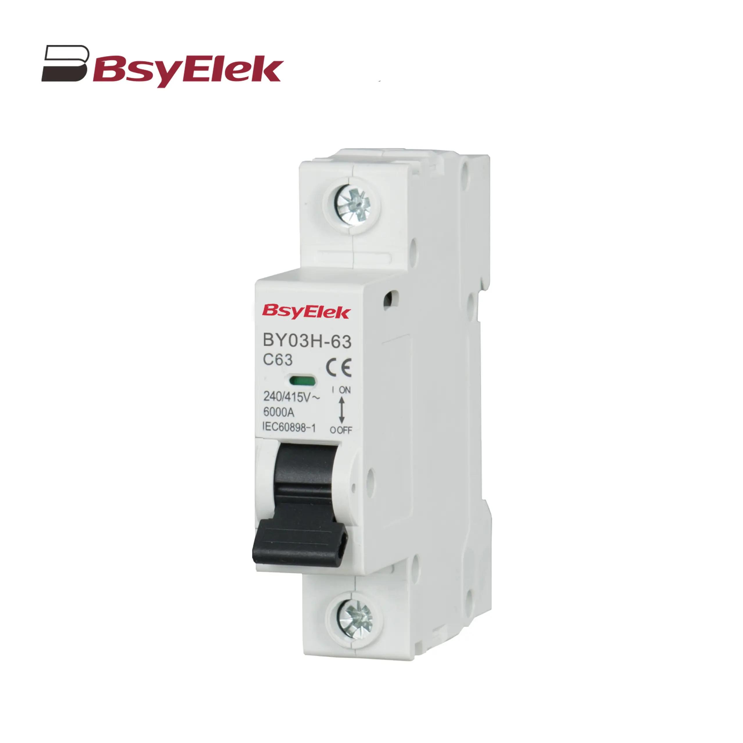
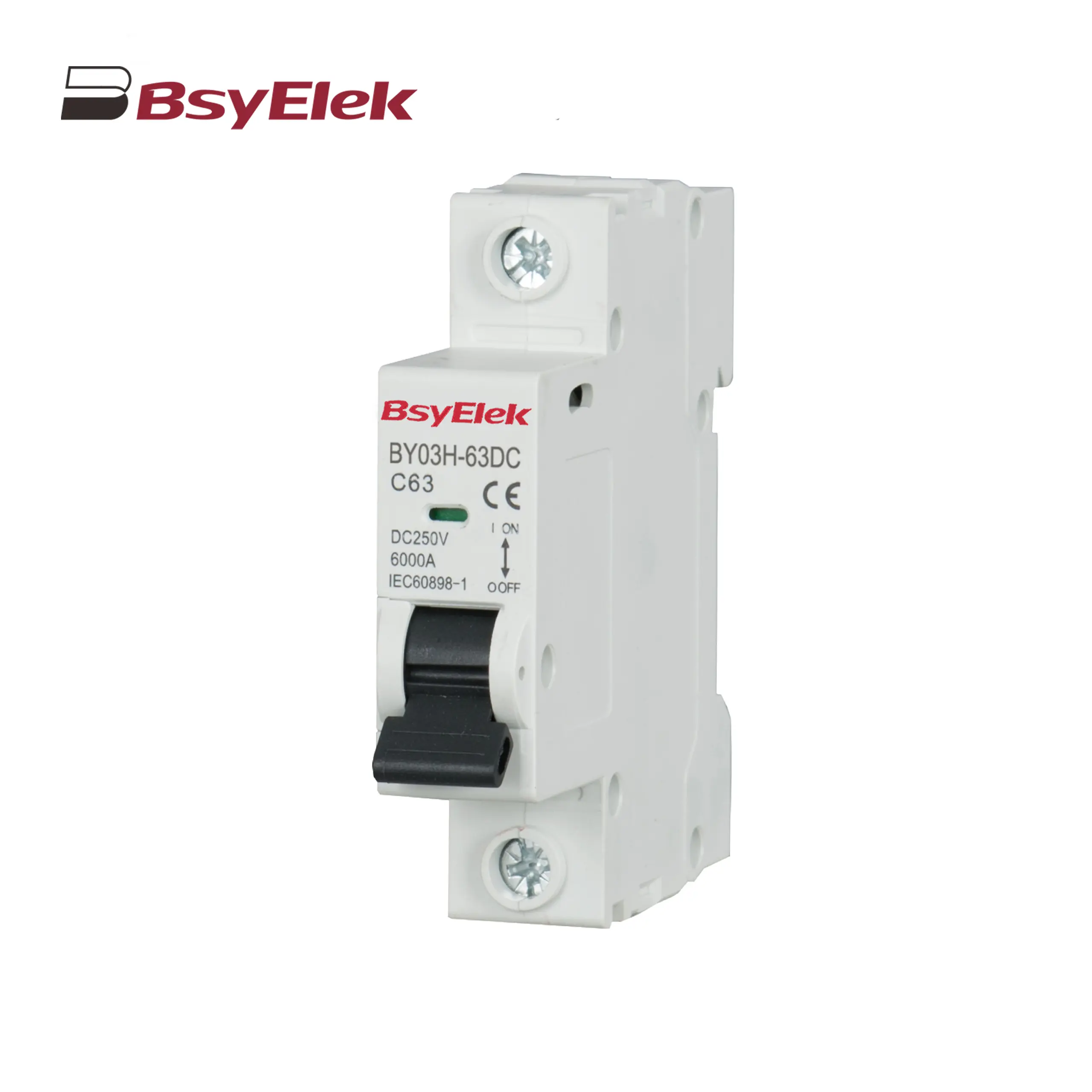
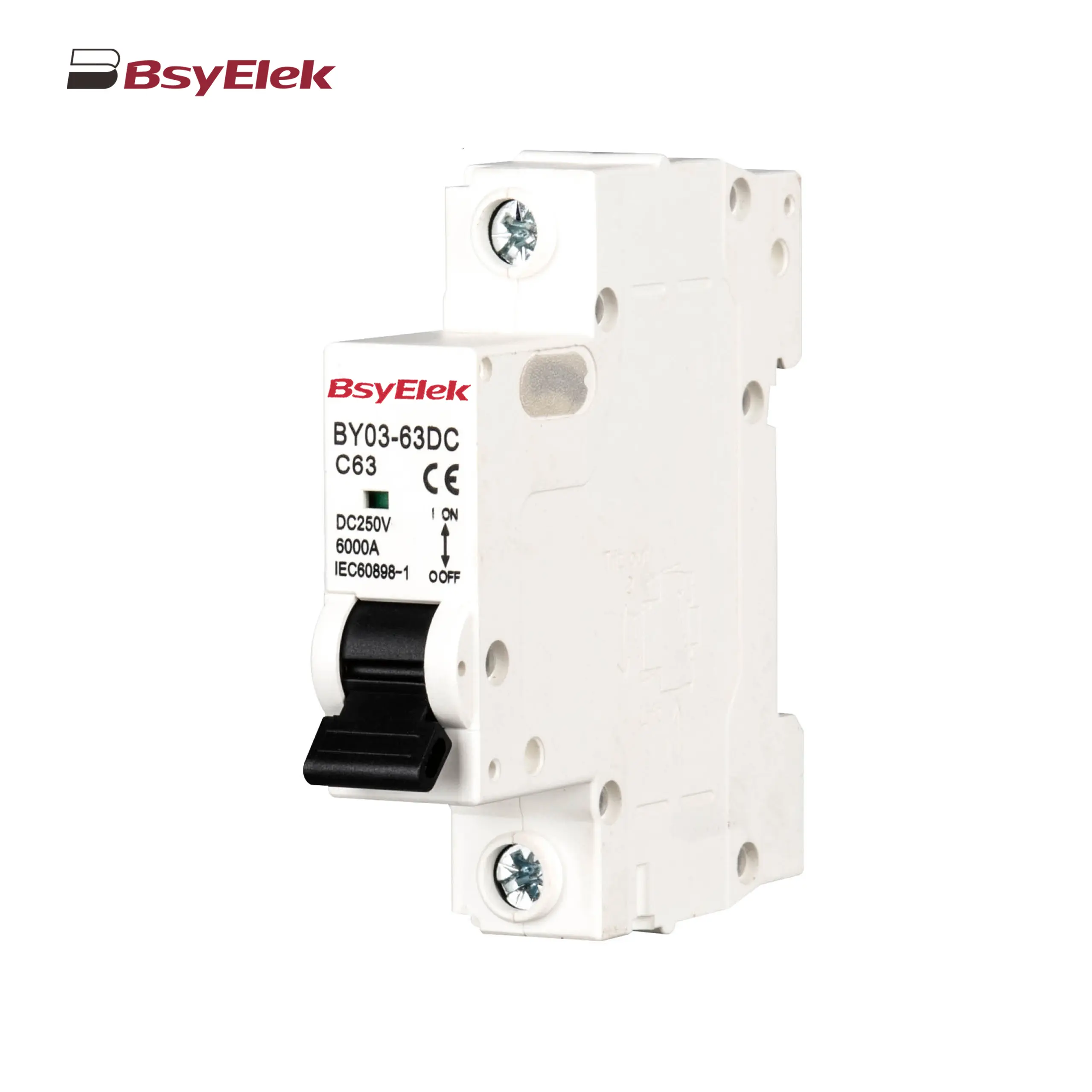
BY03H-63 MCB 6KA Miniature Circuit Breaker
BY03-63 MCB 4.5KA Miniature Circuit Breaker
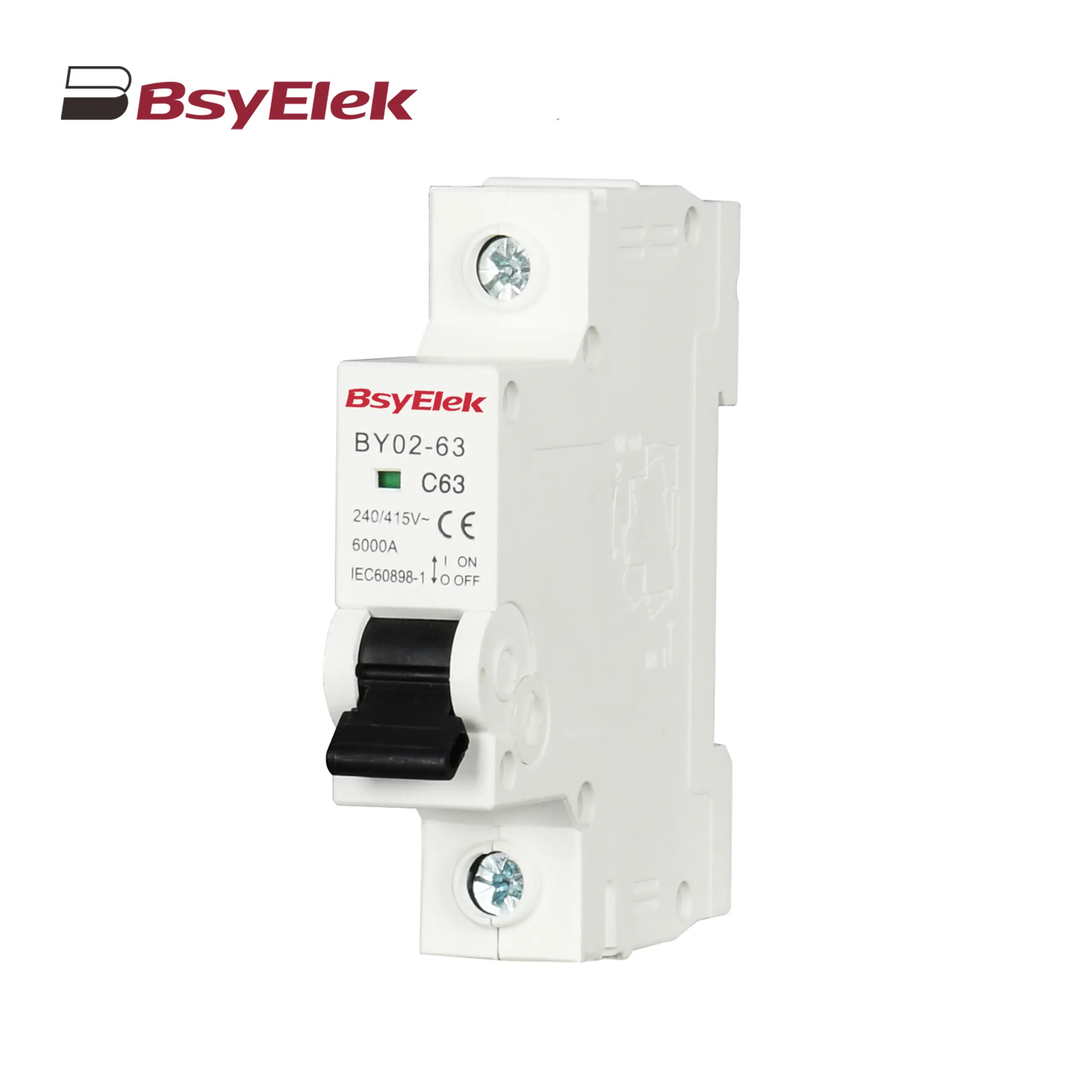
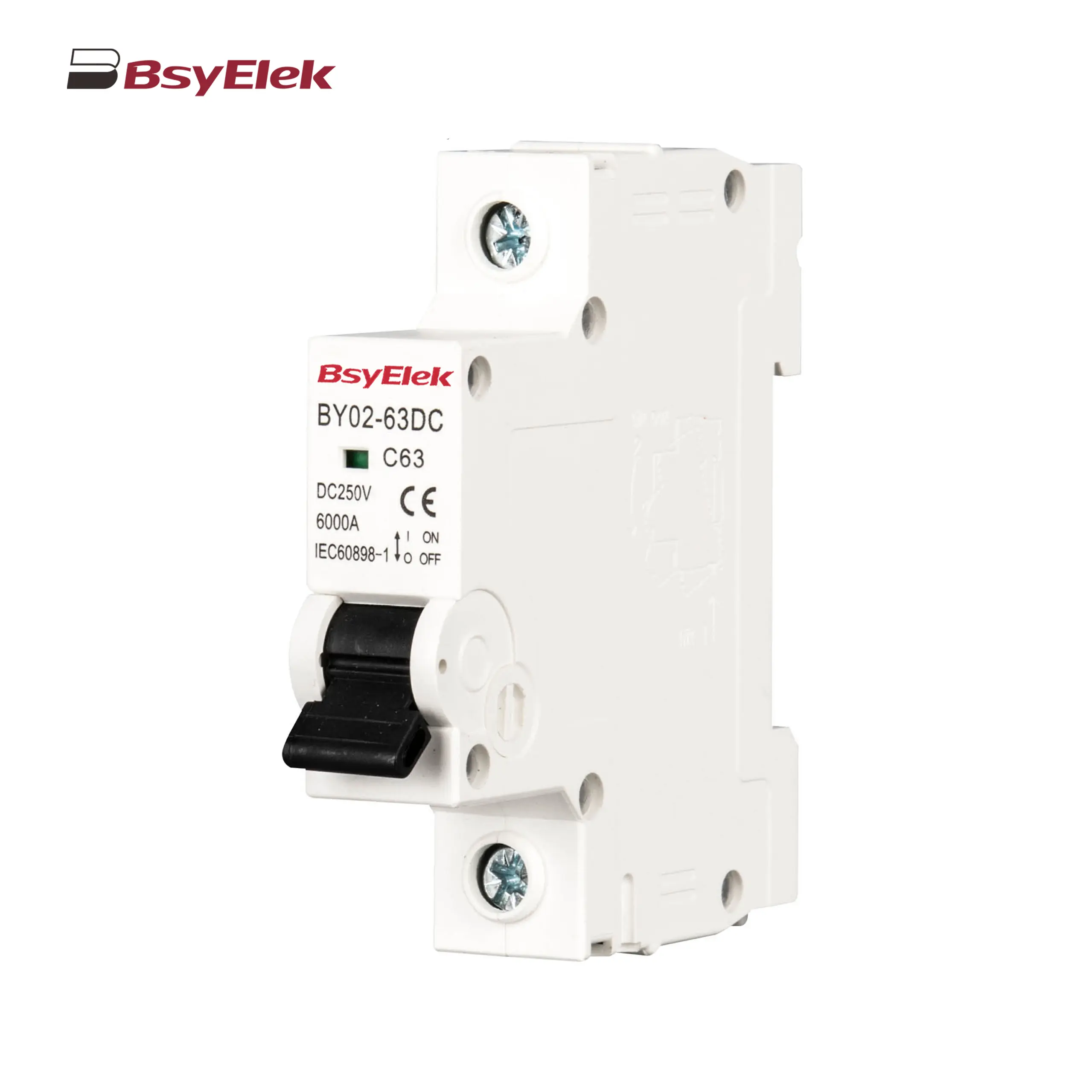
BY02-63 MCB 3kA Miniature Circuit Breaker
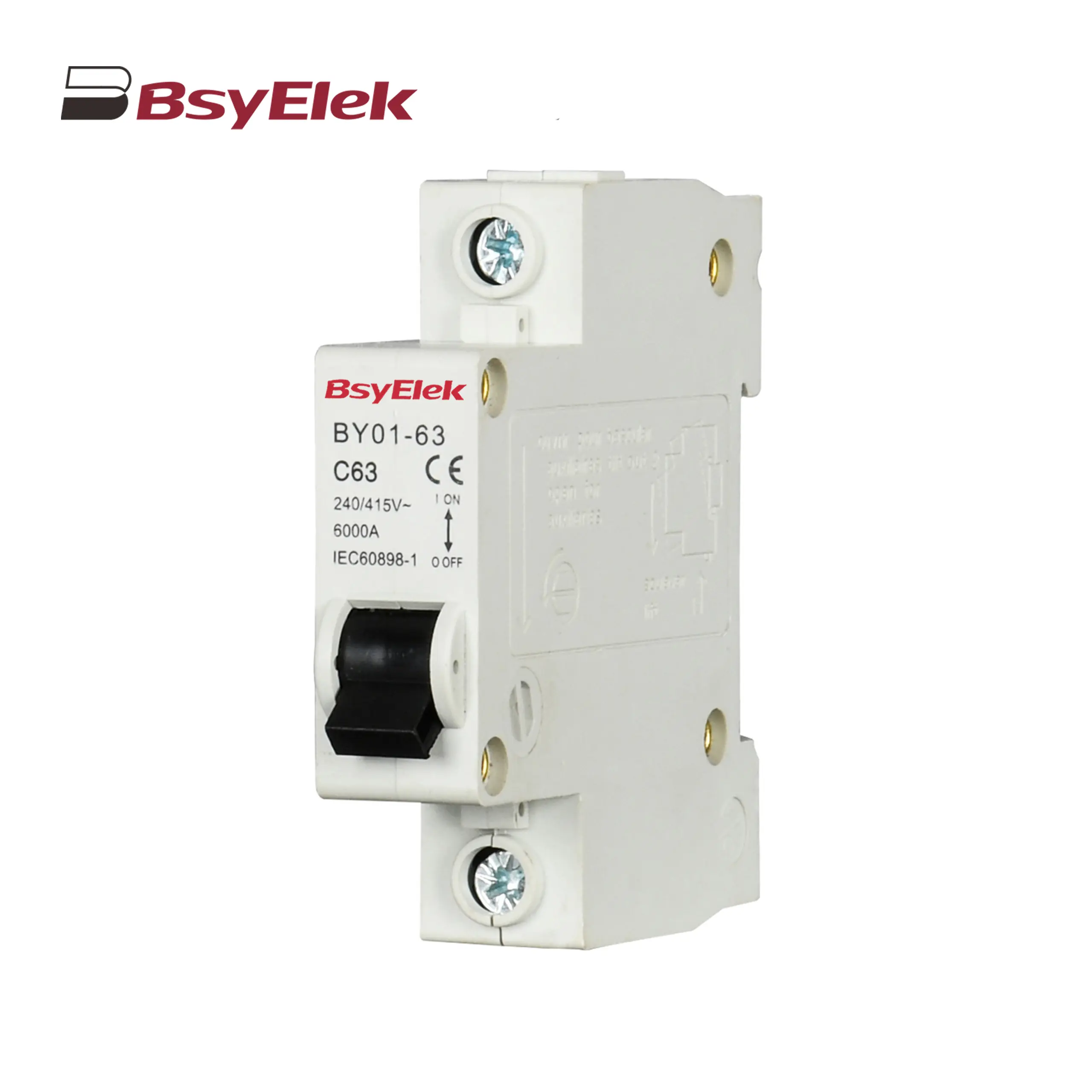
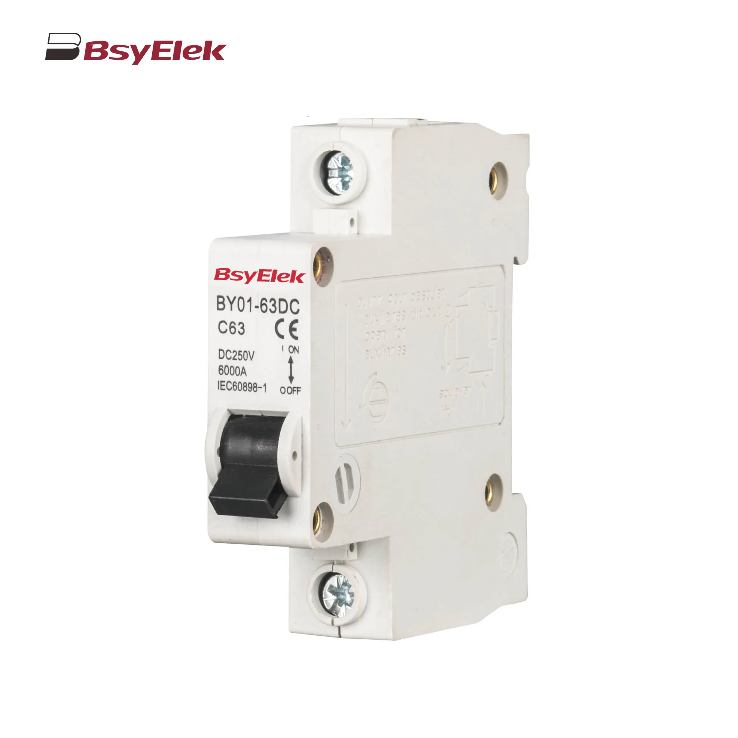
BY01-63 MCB 3kA Miniature Circuit Breaker
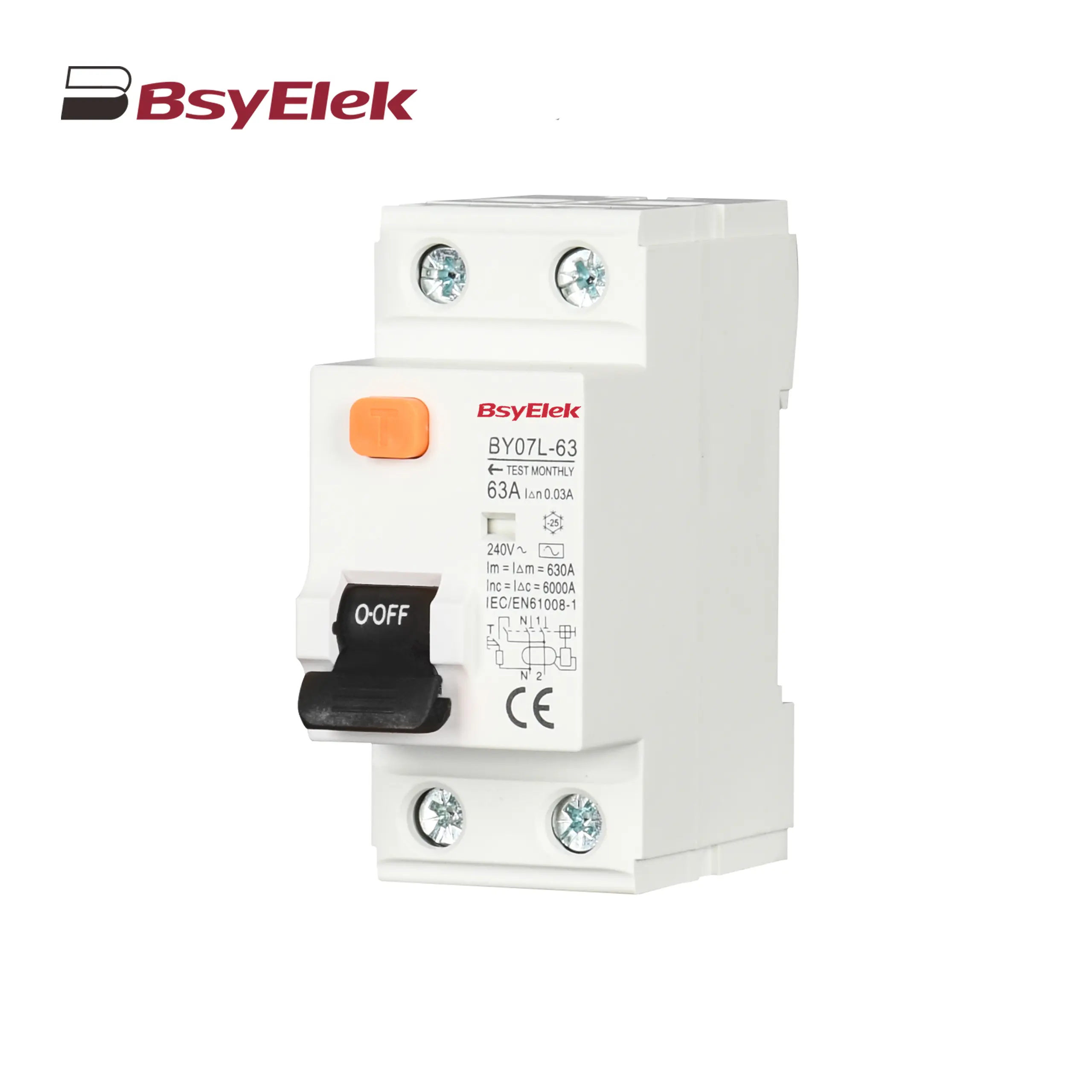
BY07L-63 RCCB 6KA Residual Current Circuit Breaker
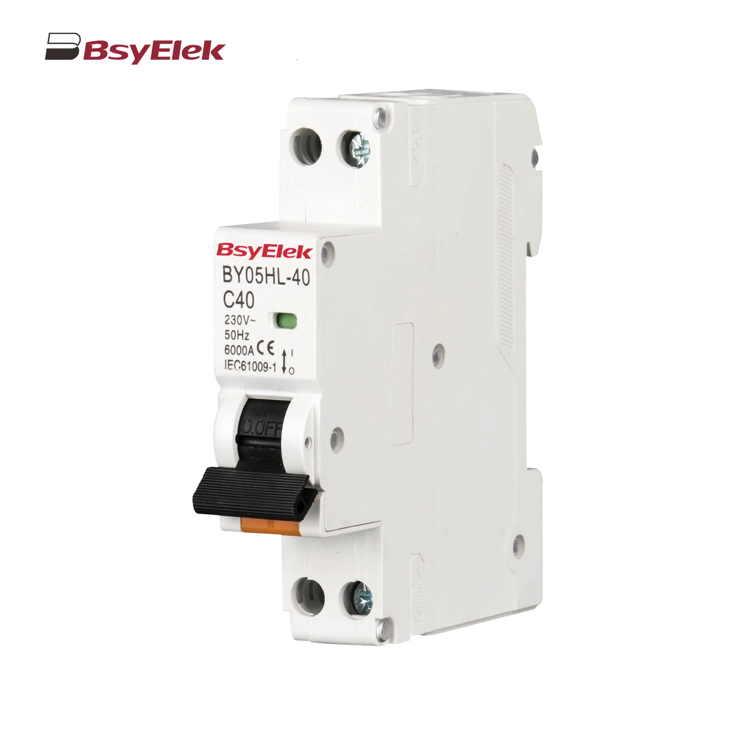
BY05HL-40 RCBO 6KA Residual Current Circuit Breaker with Over-current Protection
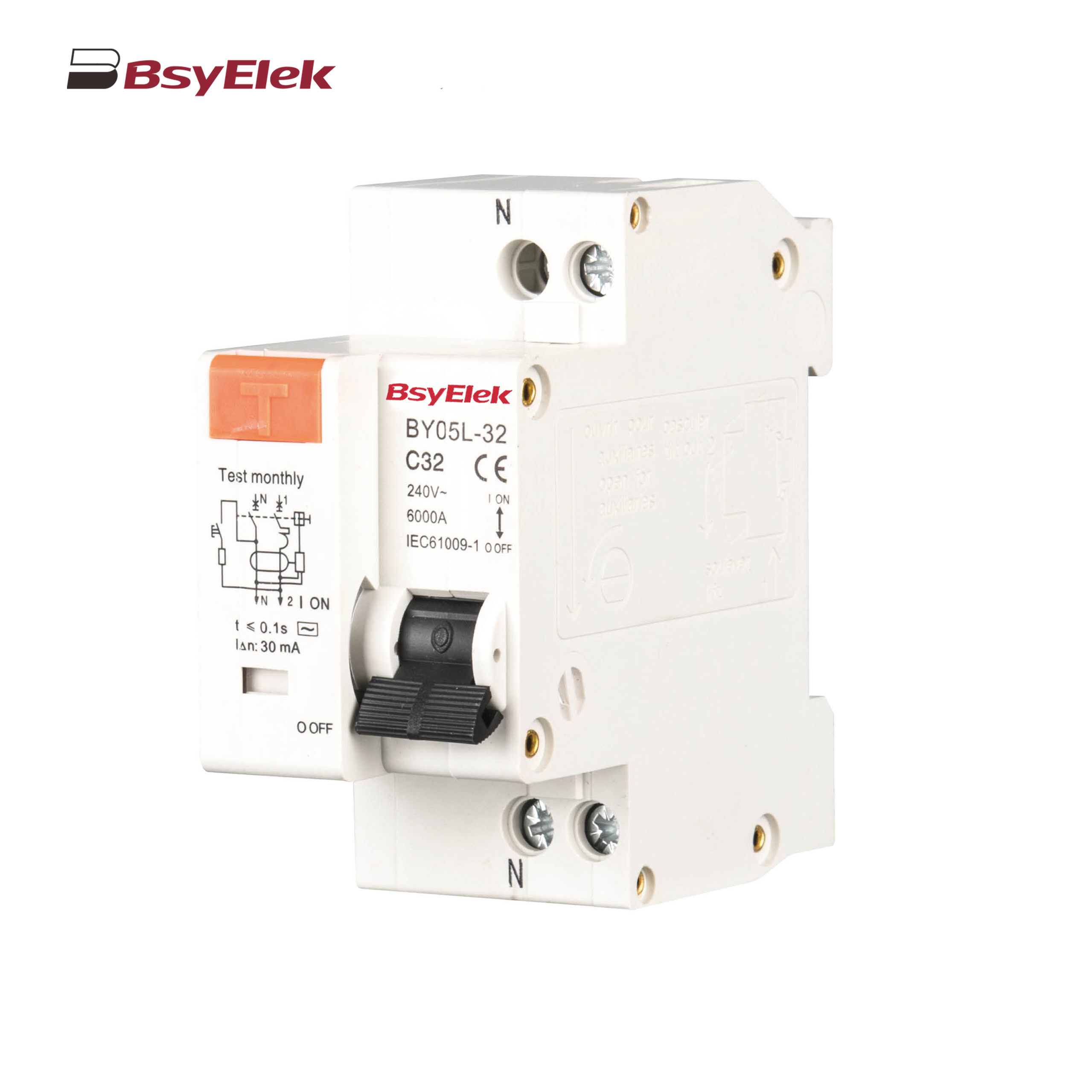
BY05L-32 RCBO 3KA Residual Current Circuit Breaker with Over-current Protection
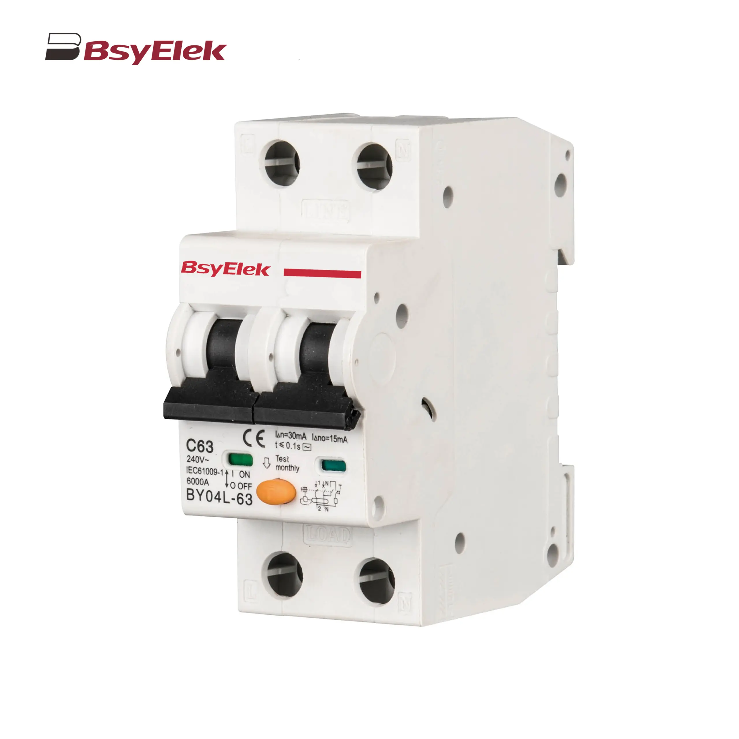
BY04L-63 RCBO 6KA Residual Current Circuit Breaker with Over-current Protection
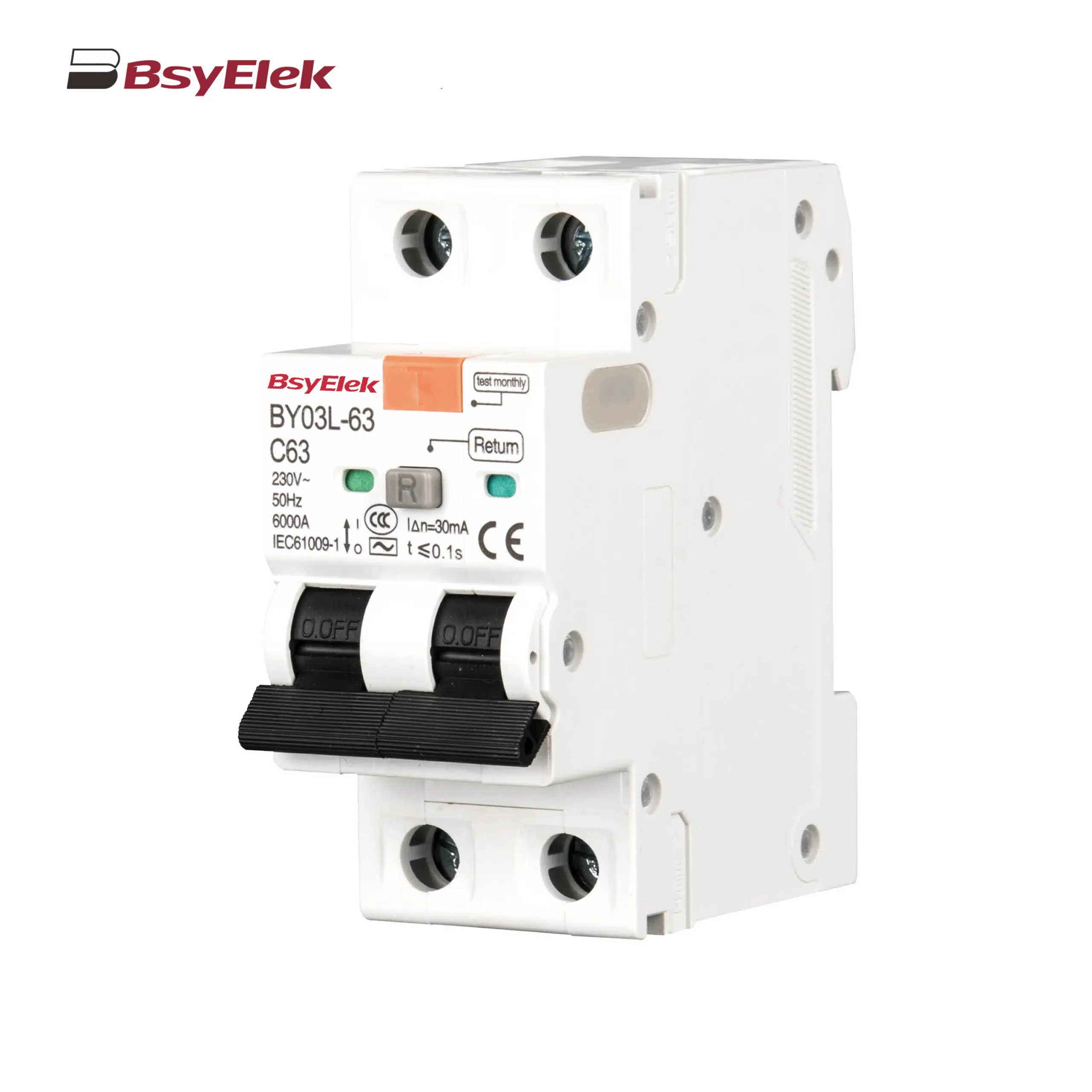
BY03L-63 RCBO 4.5KA Residual Current Circuit Breaker with Over-current Protection
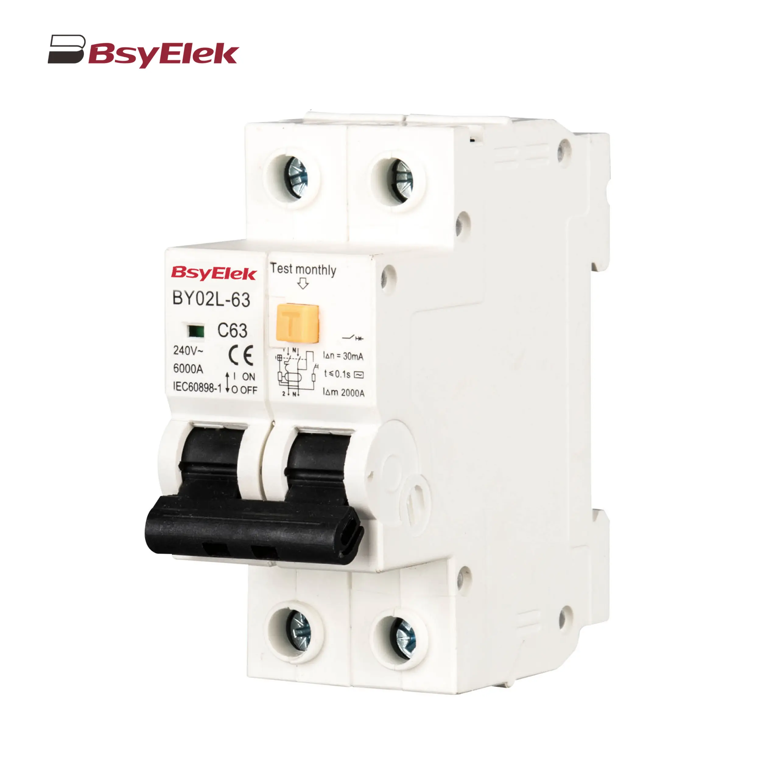
BY02L-63 RCBO 3KA Residual Current Circuit Breaker with Over-current Protection
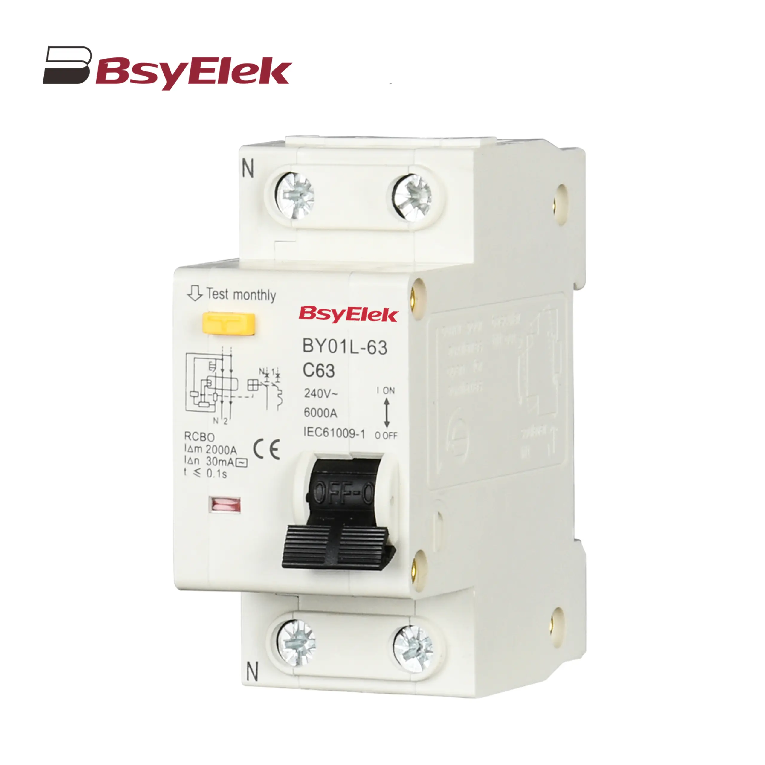
BY01L-63 RCBO 1P+N 3KA Residual Current Circuit Breaker with Over-current Protection
BY06H-125DC MCB 10-15kA DC Miniature Circuit Breaker
BY06-125DC MCB 6kA DC Miniature Circuit Breaker
BY04-63DC MCB 6-10kA DC Miniature Circuit Breaker
BY03H-63DC MCB 6kA DC Miniature Circuit Breaker
BY03-63DC MCB 4.5kA DC Miniature Circuit Breaker
BY02-63DC MCB 3kA DC Miniature Circuit Breaker
BY01-63DC MCB 3kA DC Miniature Circuit Breaker
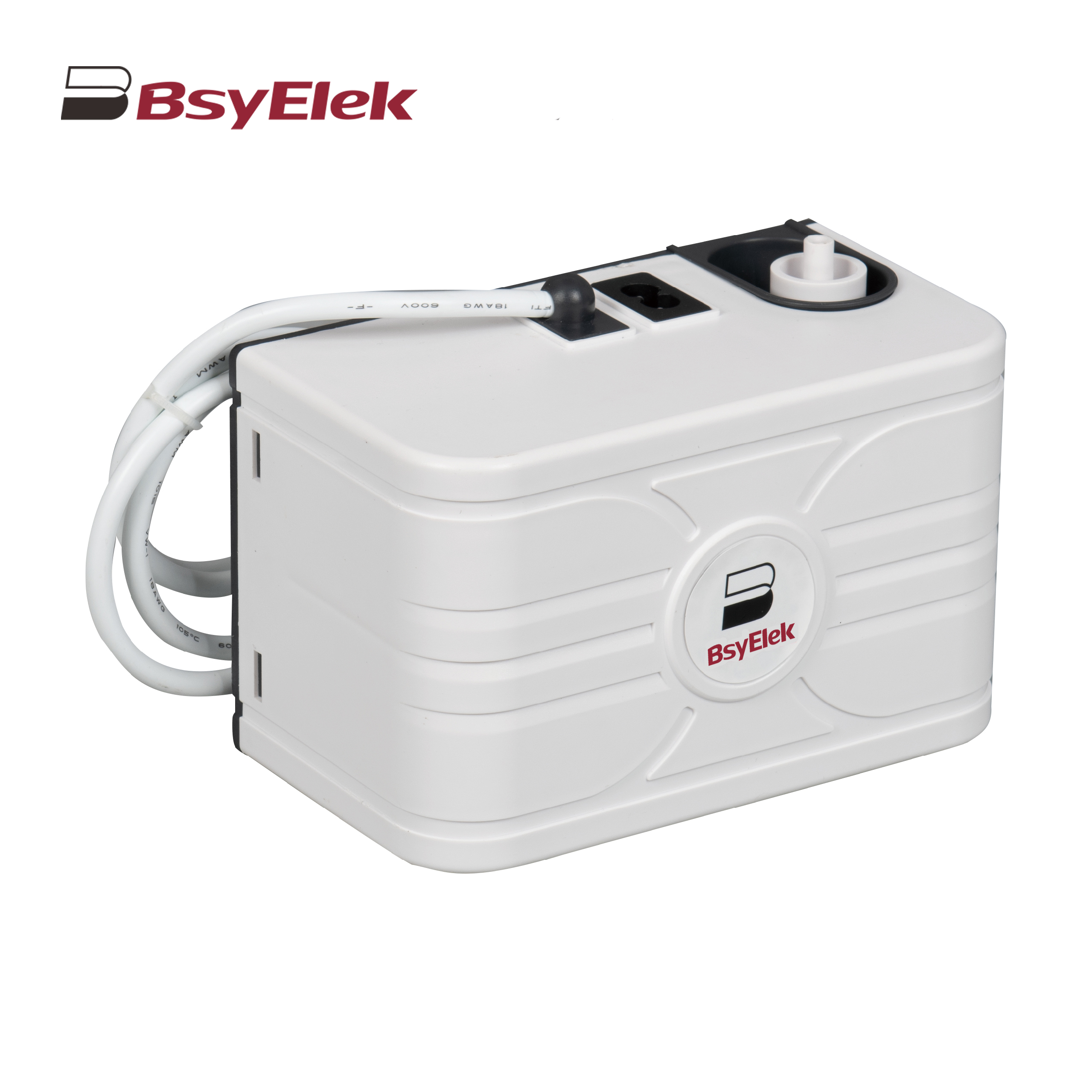
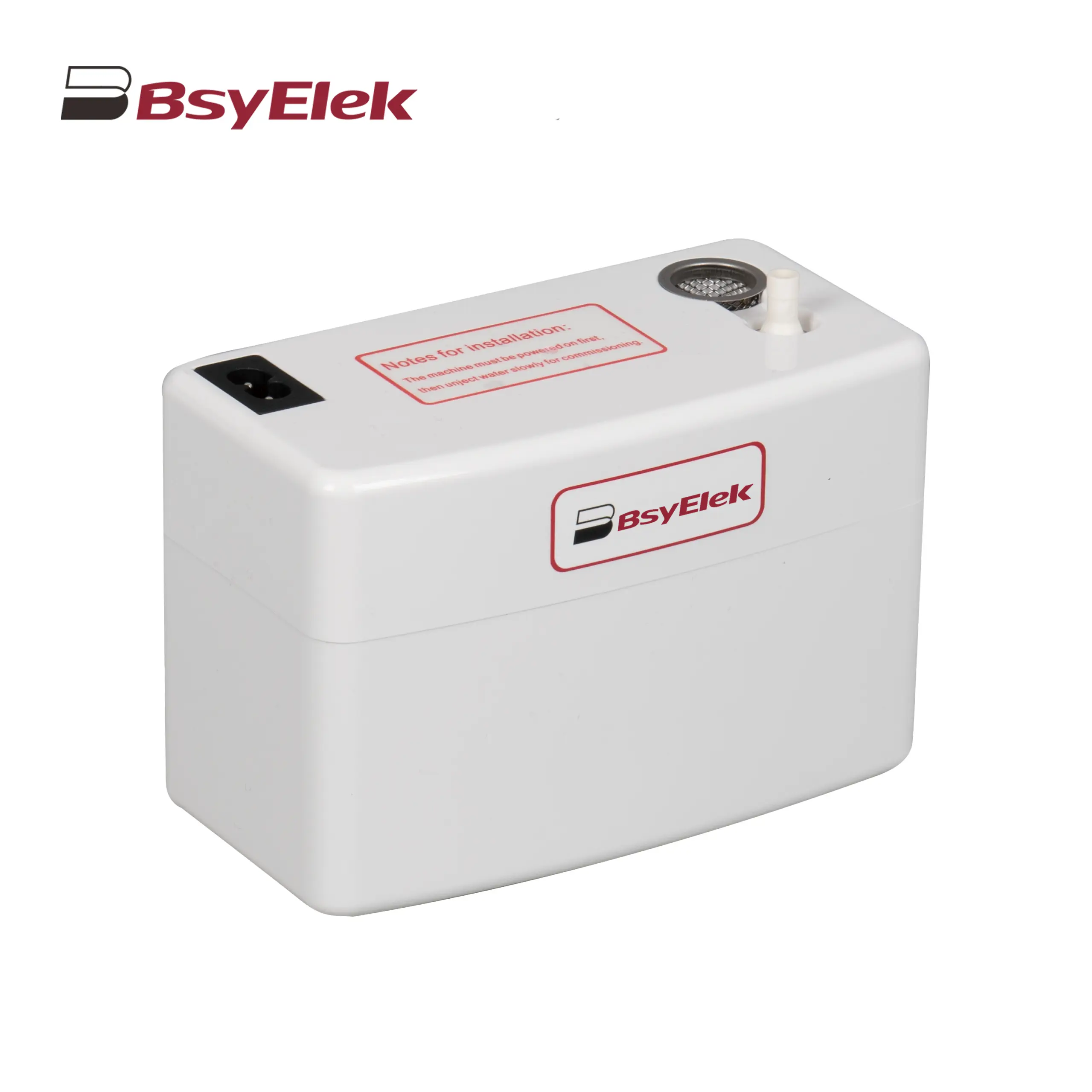
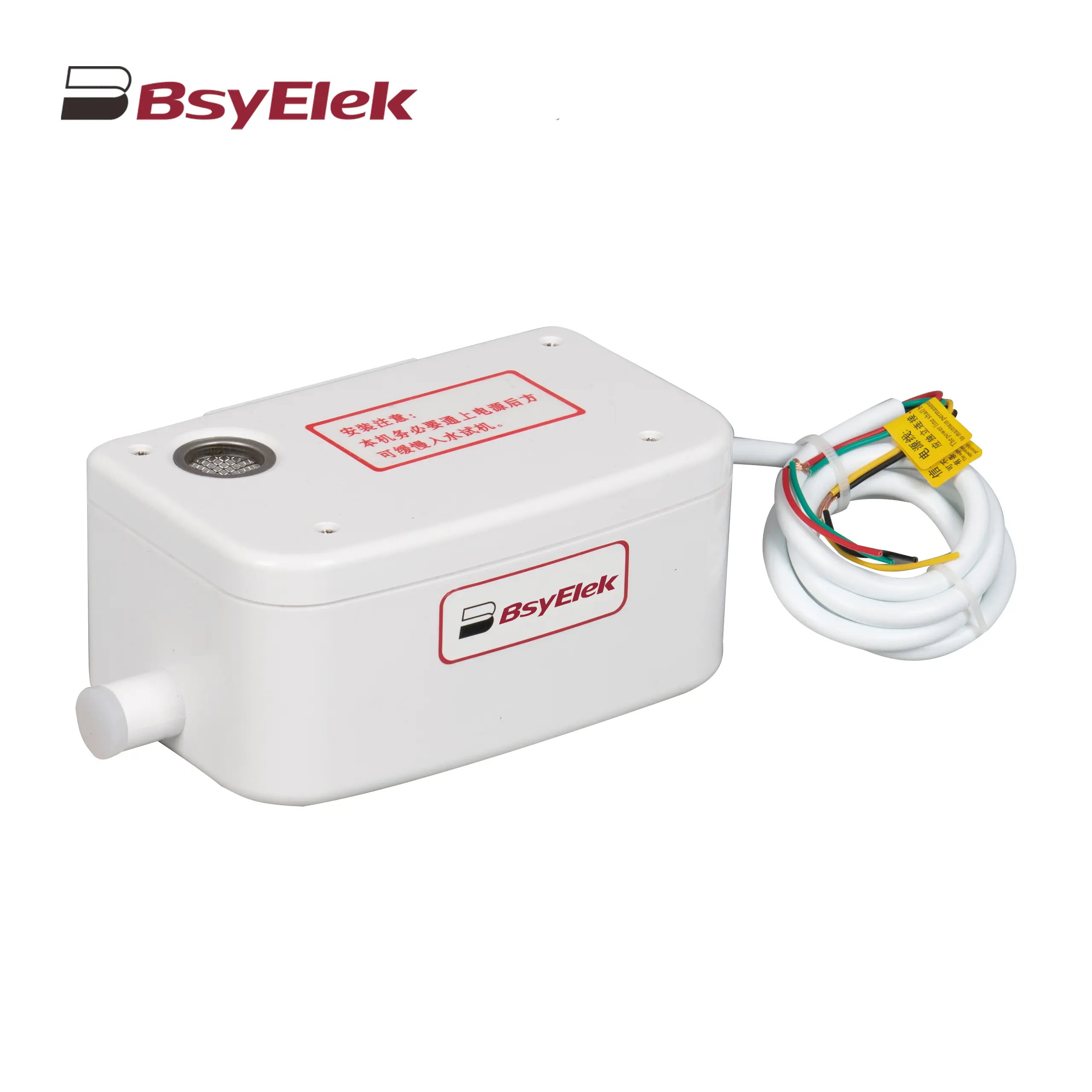
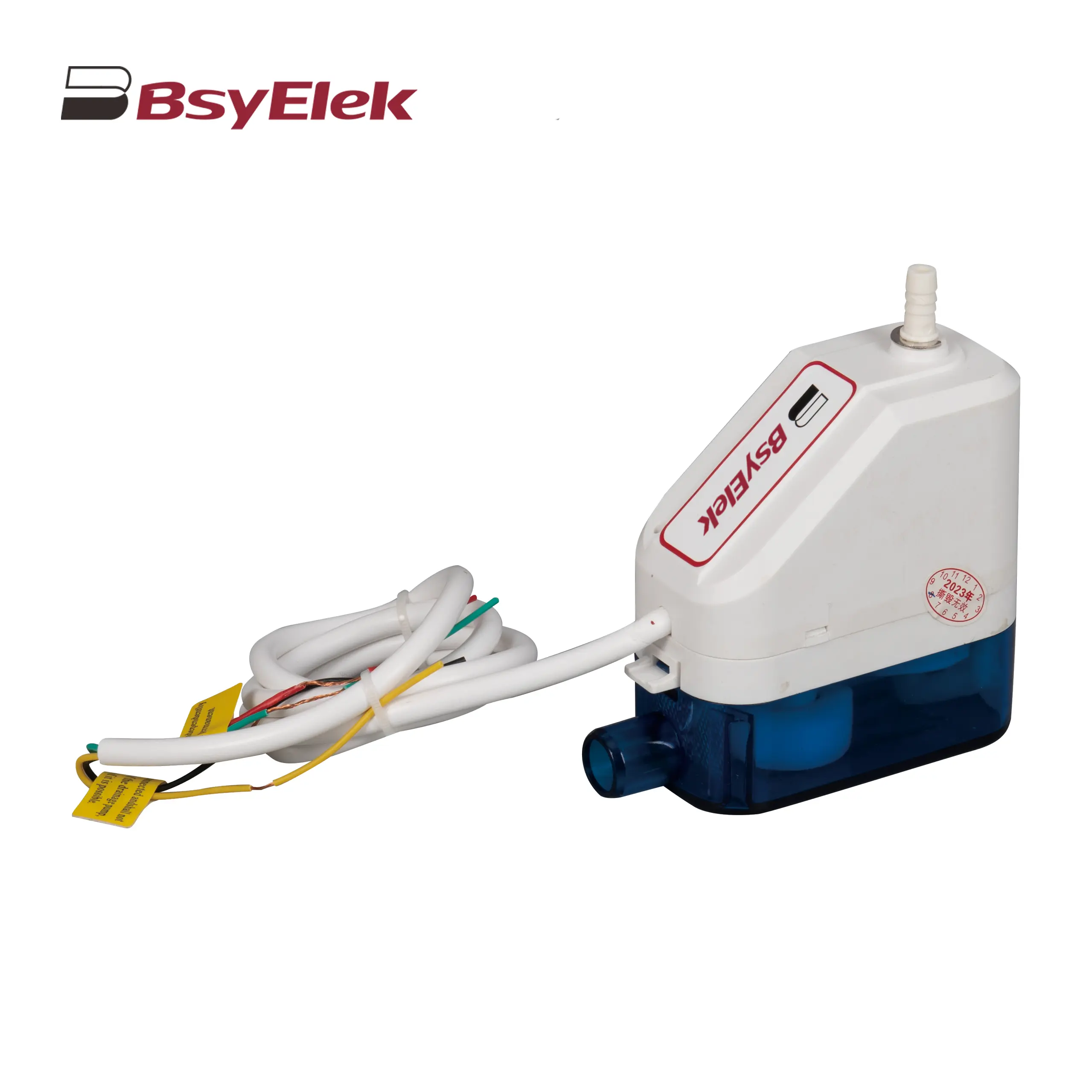
BY-5018 1.8M Engineering Drainage Pump
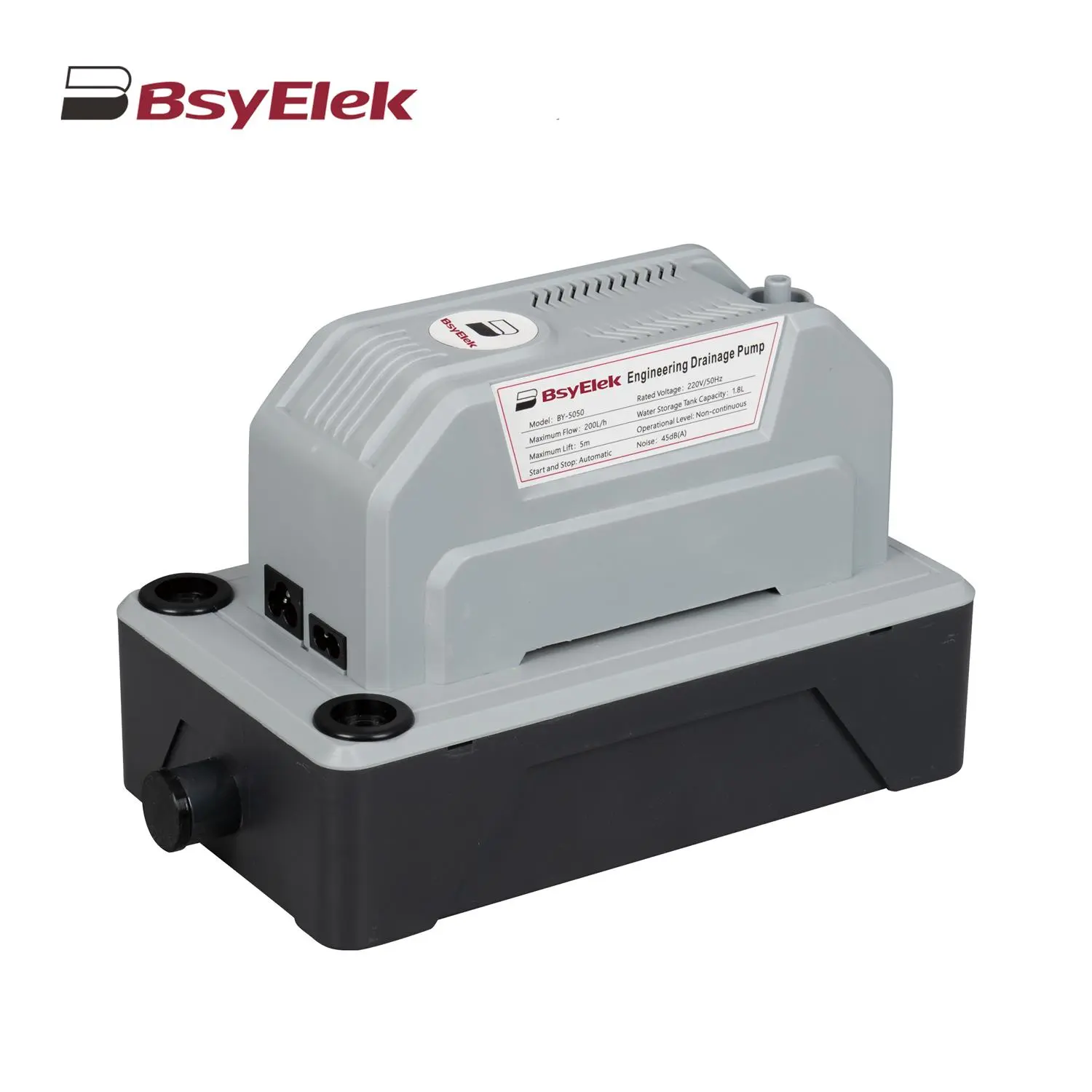
BY-5050 5M Engineering Drainage Pump
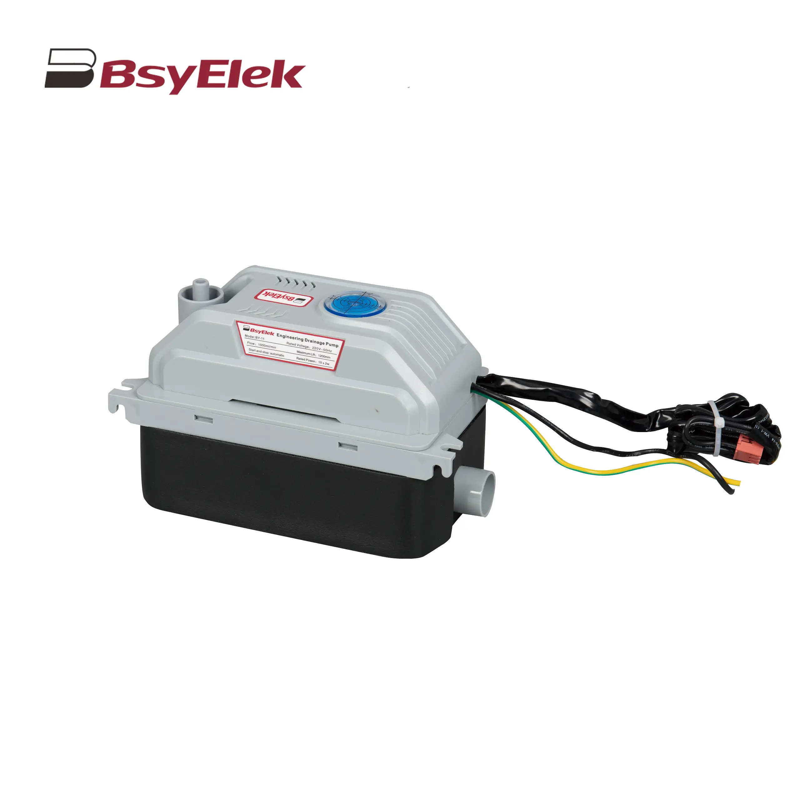
BY-11 1.2M Engineering Drainage Pump
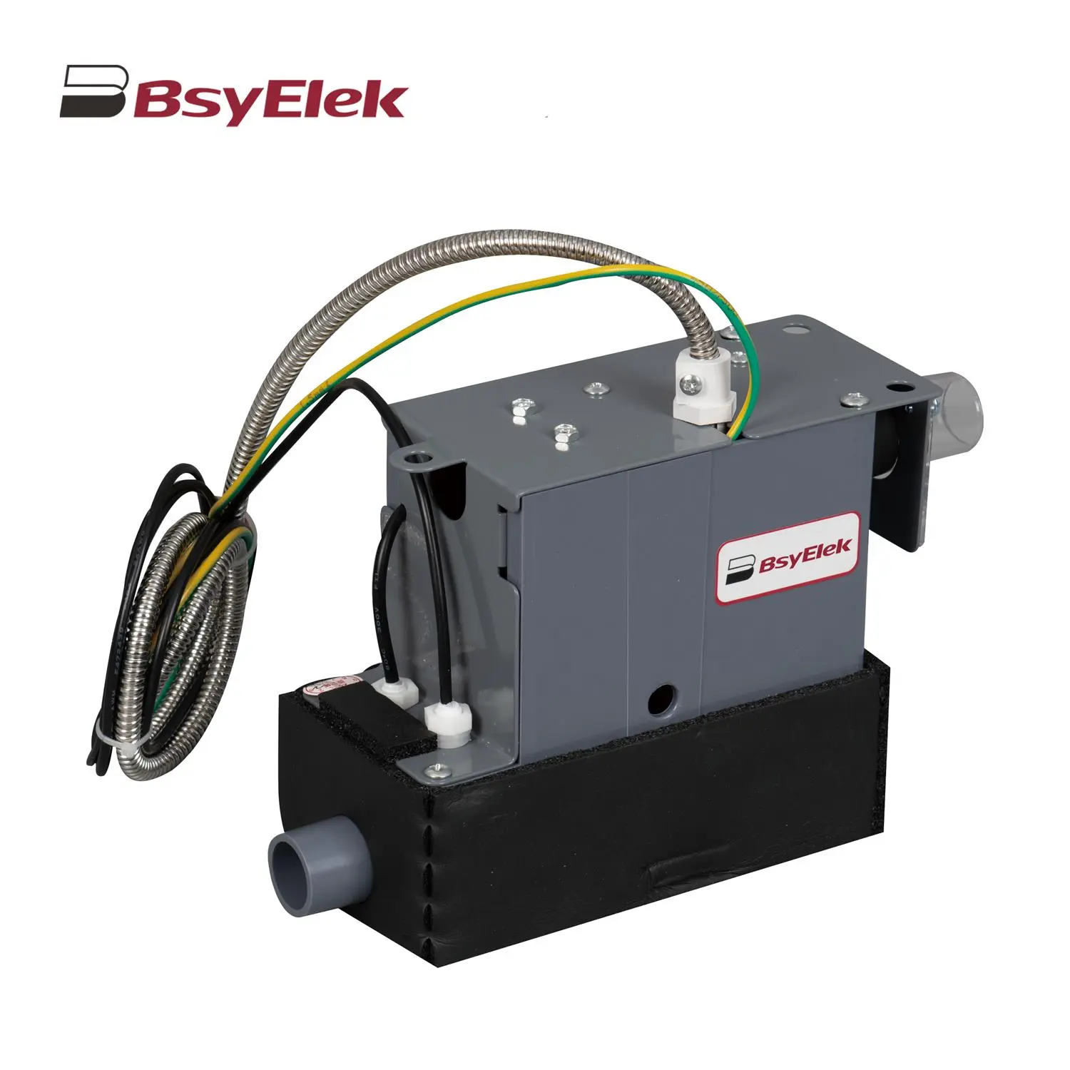
SBH-05 0.7M Original Drainage Pump of Duct Type Air Conditioner
BY-24A/40A 10M Drainage Pump of Air Conditioner
BY-50A 12M Drainage Pump of Air Conditioner
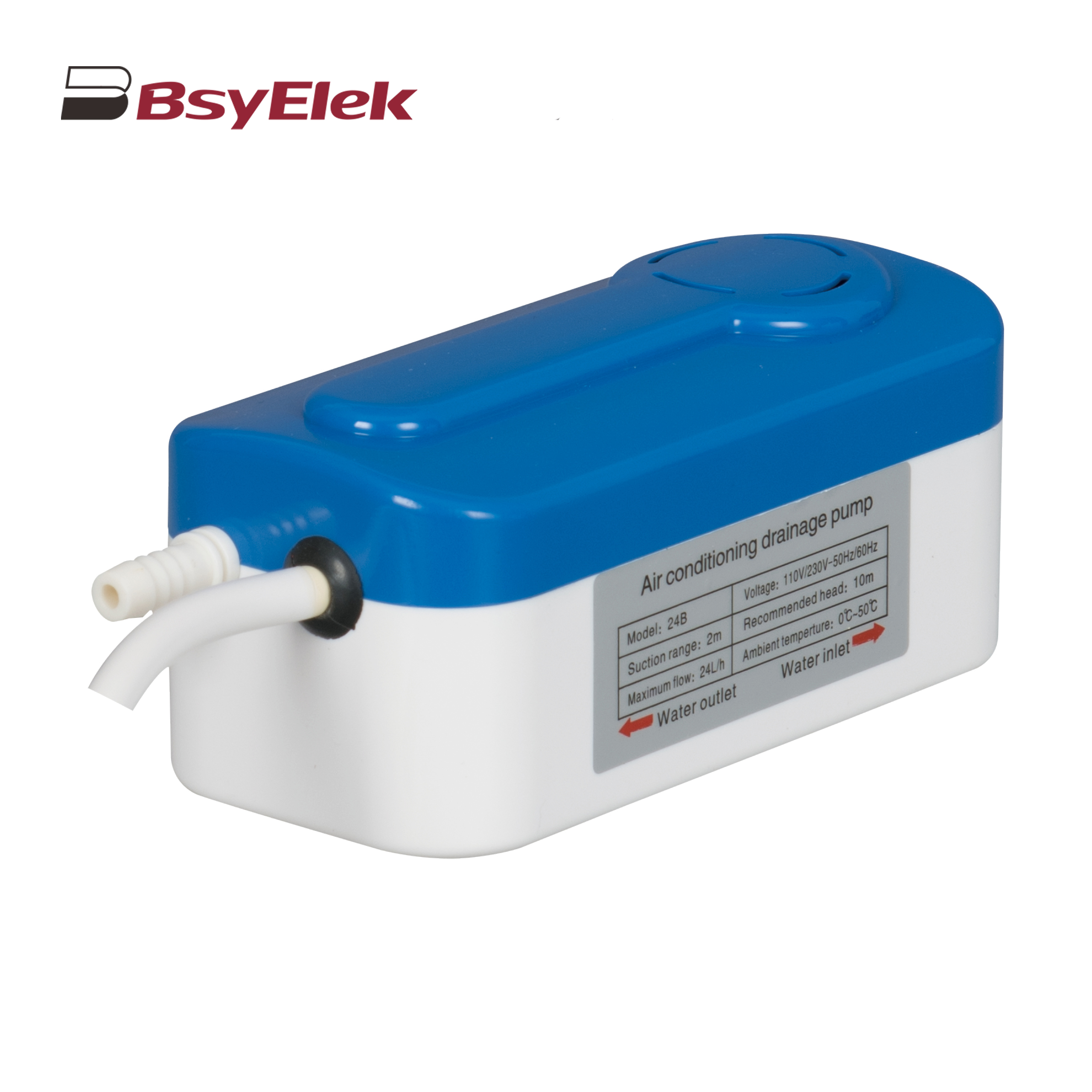
BY-24B/40B 10M Split Type Drainage Pump
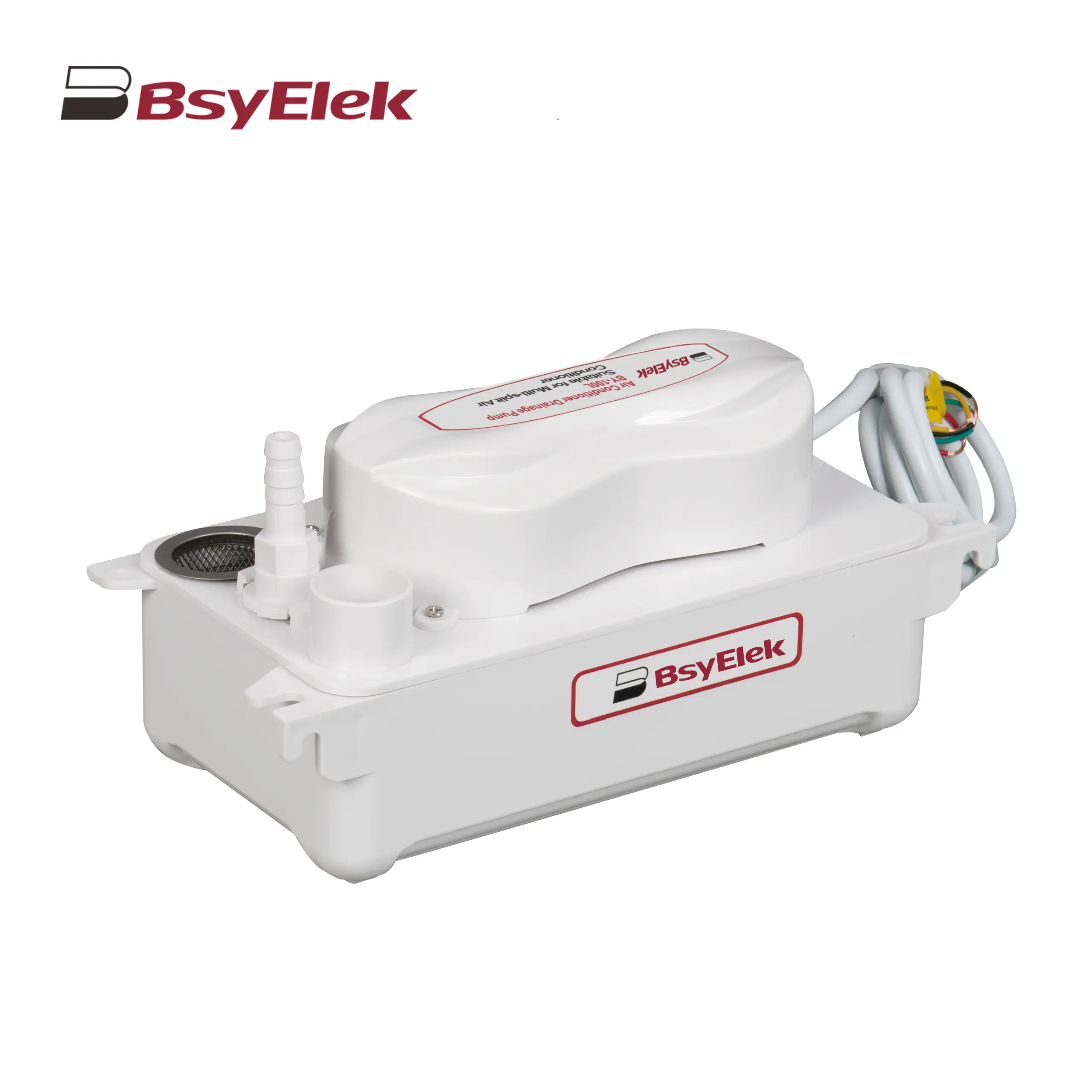
BY-100L 2M Drainage Pump of Air Conditioner
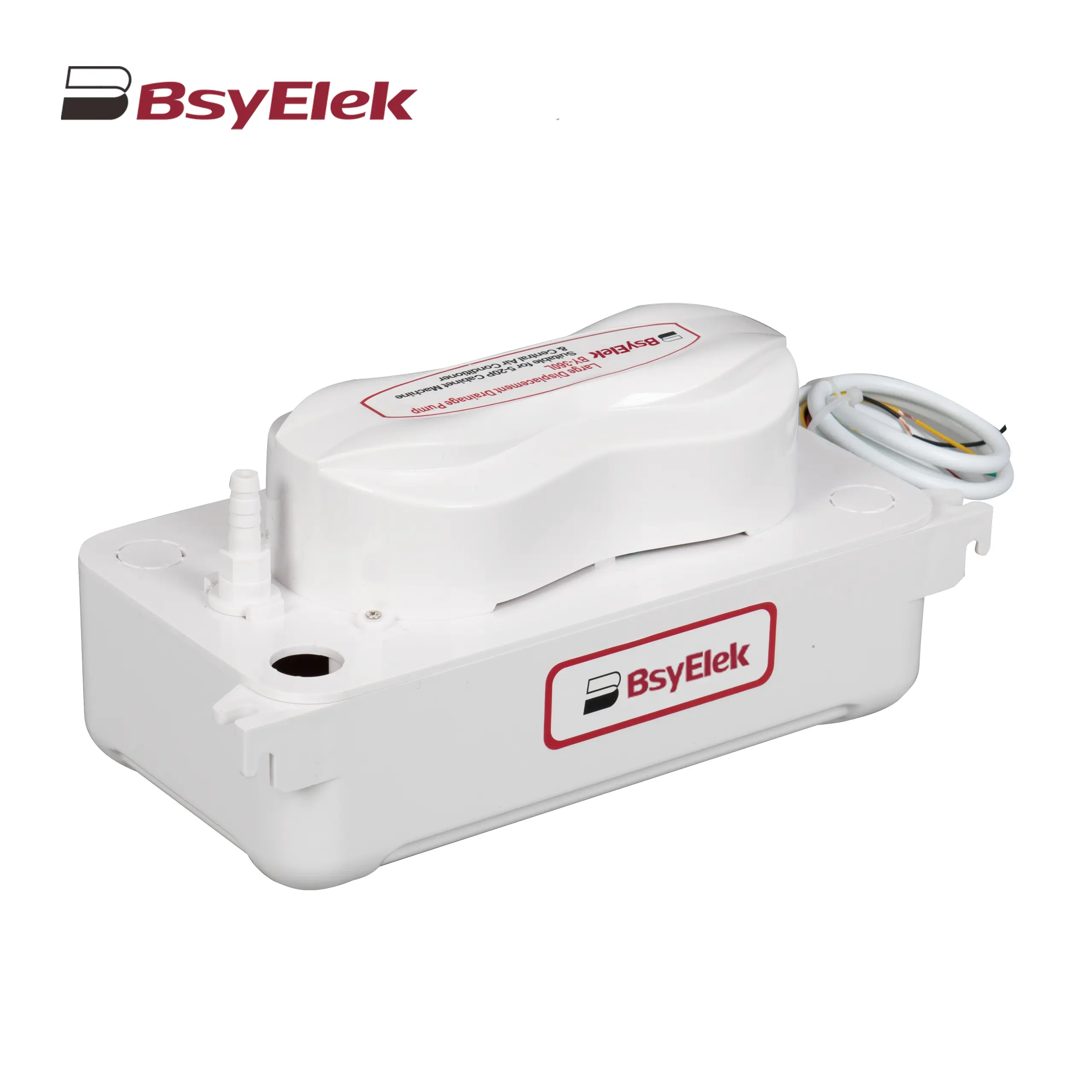
BY-360L 6M Large Displacement Drainage Pump
BY-24C/40C 10M Corner Drainage Pump
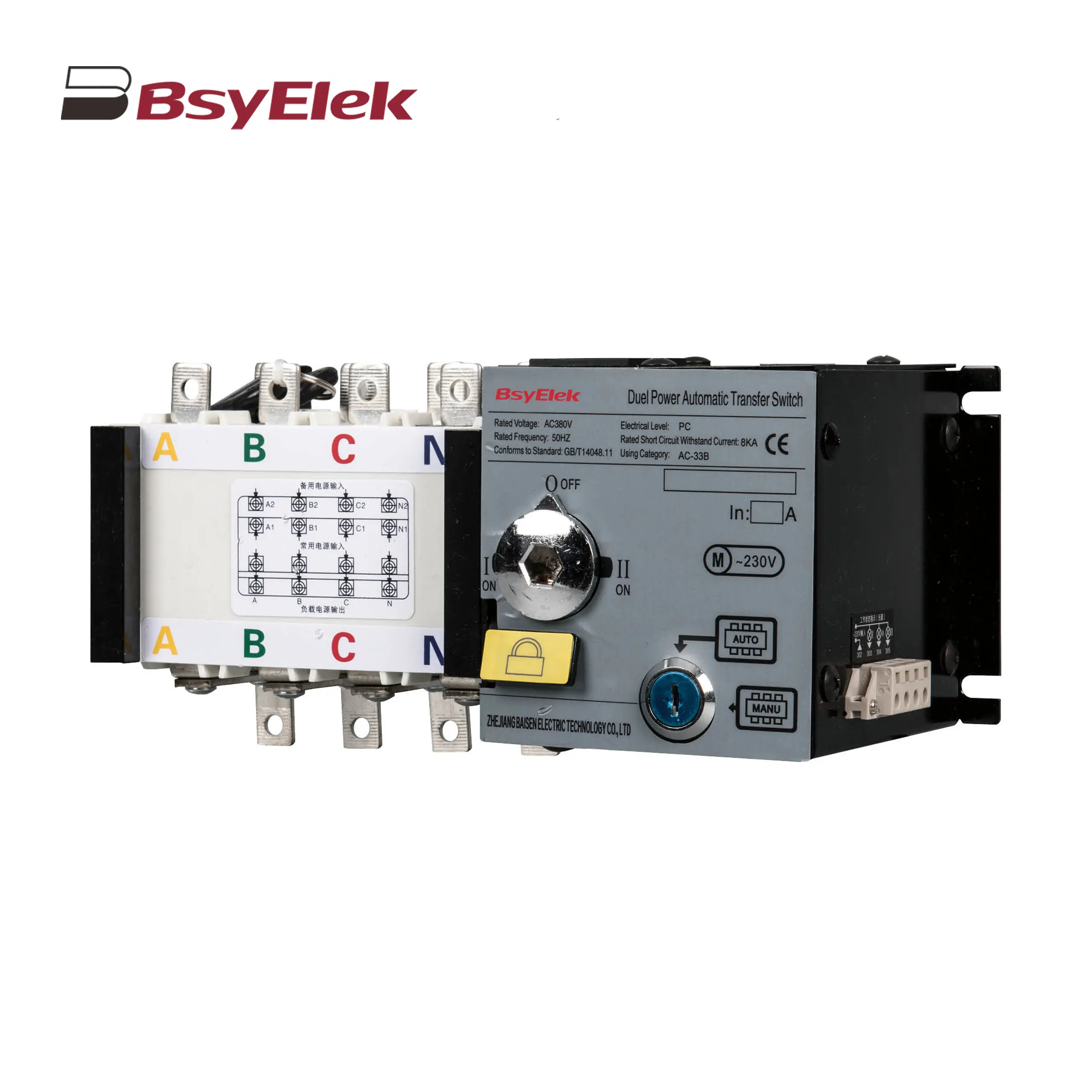
Selecting a Dual Power Automatic Transfer Switch is not a box-ticking exercise. It is a decision about continuity, safety, and recovery when utility power disappears. A hospital corridor, factory control panel, or server room may have only seconds before failure becomes expensive. The right switch must respond quickly, transfer safely, and return power without creating a second problem.
Electrical engineer and code educator Mike Holt often reminds professionals, “Safety is not an option.” That principle should guide every specification. Buyers need to examine load type, voltage, current rating, transfer time, short-circuit withstand, enclosure protection, and maintenance access. A switch that fits the cabinet may still fail the application. That detail is easy to miss.
This guide presents seven practical tips for choosing a Dual Power Automatic Transfer Switch. It considers generator compatibility, neutral switching, controller functions, bypass-isolation features, environmental conditions, certifications, and supplier support. Real installation conditions matter. Dust, heat, vibration, and limited working space can change the best choice.
Experience also suggests a more careful question: what happens after the transfer? Operators need clear indicators, event records, manual controls, and a simple testing routine. A sophisticated controller is not automatically a dependable one. Sometimes, simpler is better.
Specifications can be imperfect. Site measurements may be incomplete. Future loads may grow. Therefore, engineers should verify assumptions with qualified professionals and applicable electrical standards. Reliable selection comes from comparing documented performance, not trusting attractive claims. The following tips are designed to make that comparison more practical, visible, and defensible.
Before selecting a dual power automatic transfer switch, define the load it must carry. Record system voltage, phase arrangement, frequency, and maximum continuous current. Include lighting, pumps, servers, heaters, and control circuits separately. A nameplate rating alone can mislead. Motors may draw five to seven times their running current during startup. Transformers and capacitors can also create brief inrush peaks. Measure actual demand with a power-quality analyzer when possible, rather than relying on old drawings. Field conditions often differ.
Check the normal and standby sources under the same load conditions. Confirm that both sources provide compatible voltage, frequency, phase sequence, and neutral treatment. Size the switch for continuous current, not only the average reading. Review short-circuit withstand ratings with a qualified electrical engineer. Consider ambient heat, enclosure ventilation, altitude, cable length, and future expansion. A 400-ampere load may need more capacity if a large pump starts during transfer. I once saw a transfer plan pass paper review but fail during generator testing because the starting surge was omitted. That mistake was preventable. Do not assume every load transfers safely. Some equipment needs delayed sequencing, bypass arrangements, or a separate critical-load panel. Verify transfer-time requirements according to applicable codes and site procedures. Keep records of measured current, startup behavior, and protection settings.
Check voltage, current, and phase before comparing features. A switch rated for 400 volts may fail in a 415-volt system. Confirm both source voltage and the equipment’s allowable voltage range. The U.S. Energy Information Administration reports that 60 Hz dominates North American grids, while many regions use 50 Hz. Frequency matters. Mismatches can damage motors and controls.
Match the switch’s continuous current rating with the load, including motor starting current. A 100-ampere panel may briefly demand far more during startup. Review the short-circuit current rating, too. IEC 60947-6-1 provides requirements for transfer switching equipment and coordination. Uptime Institute’s 2024 outage analysis reported that power problems contributed to about 52% of data-center outages. Small selection errors can become expensive downtime.
Check whether the system is single-phase or three-phase, then verify phase sequence and neutral switching. An incorrect sequence can make a three-phase motor rotate backward. Confirm generator and utility terminals separately. Field inspections often reveal mislabeled conductors, even in recently installed panels. That is uncomfortable, but real. Also check insulation voltage, transfer time, enclosure rating, and control compatibility. NFPA 110 emphasizes reliable emergency power performance and regular testing. A spreadsheet can still lie; measure the actual load, record peak current, and test both sources under controlled conditions.
A dual power automatic transfer switch must move loads quickly, but speed alone is not enough. NFPA 110 identifies a Type 10 emergency power system, requiring power availability within 10 seconds for applicable installations. However, the switch may transfer much faster. During commissioning, measure actual interruption time with a power-quality analyzer, not only the catalogue value.
Tip 1: Check transfer speed under realistic load. Test resistive, inductive, and electronic loads separately. A switch that performs well without load may respond differently beside motor starters or UPS equipment. IEC 60947-6-1 provides a technical framework for transfer switching equipment, including operating and endurance considerations. Review phase sensing, undervoltage settings, frequency limits, and adjustable time delays. Tiny delays matter.
Tip 2: Examine switching performance during unstable utility conditions. The controller should avoid unnecessary transfers caused by brief voltage dips. Confirm break-before-make or closed-transition behavior, depending on the load and installation design. Uptime Institute’s 2024 Annual Outage Analysis reported that 54% of surveyed outages caused costs above $100,000. That figure is a useful warning, although outage surveys do not predict every facility’s risk. Tip 3: Demand documented tests for transfer, retransfer, manual bypass, and source failure. Record waveform disturbance, contact bounce, and recovery time. I would not accept a fast specification without field evidence. Real installations are messier. A poorly tuned delay can defeat an otherwise capable switch.
| Tip | Evaluation Dimension | Practical Data or Recommended Range | Why It Matters | How to Verify |
|---|---|---|---|---|
| 1 | Transfer time | Typical open-transition transfer: approximately 50 ms to 1,000 ms, depending on source monitoring, delay settings, and switching mechanism. | Shorter transfer time reduces interruption duration, but the required value depends on the load and whether ride-through equipment is installed. | Measure from loss of the preferred source to stable connection of the alternate source using an oscilloscope or power-quality analyzer. |
| 2 | Source monitoring accuracy | Adjustable undervoltage, overvoltage, underfrequency, and overfrequency thresholds; common voltage tolerance settings are around ±5% to ±15% of nominal. | Accurate monitoring prevents unnecessary transfers caused by brief disturbances while still detecting genuine source failures. | Compare programmed thresholds with calibrated voltage and frequency measurements under normal and fault conditions. |
| 3 | Transfer and retransfer delays | Adjustable time delays commonly range from 0 to 30 seconds for transfer and 0 to 600 seconds for retransfer, subject to system design. | Delays help avoid switching during momentary voltage dips and allow a standby source to stabilize before accepting the load. | Confirm delay resolution, actual timing accuracy, and whether settings can be locked against unauthorized changes. |
| 4 | Switching mode and transition type | Open transition disconnects one source before connecting the other; closed transition briefly overlaps sources and requires compatible phase, voltage, and frequency conditions. | The transition method determines interruption duration, synchronization requirements, and the risk of source paralleling. | Check the single-line diagram, interlocking method, synchronization controls, and the manufacturer’s permitted operating sequence. |
| 5 | Electrical and mechanical interlocking | The design should prevent both power sources from being connected simultaneously in open-transition operation, using mechanical and/or electrical interlocks. | Effective interlocking reduces the risk of source short circuits, unintended backfeed, and equipment damage. | Perform a no-load functional test, inspect the interlock mechanism, and verify that failure of a control signal cannot create an unsafe connection. |
| 6 | Switching endurance and operating class | Compare the rated electrical current, short-circuit withstand rating, utilization category, and mechanical/electrical endurance stated in the test documentation. | A switch may transfer quickly but still be unsuitable if its contacts, actuator, or fault withstand rating does not match the installation. | Review certified test reports and confirm ratings against the available fault current, load type, voltage, and expected switching frequency. |
| 7 | Load compatibility and performance verification | Verify phase configuration, nominal voltage, frequency, continuous current, neutral switching requirements, motor starting current, and non-linear load characteristics. | Incorrect sizing can cause nuisance trips, excessive contact heating, voltage disturbances, or failed transfers. | Test with representative load conditions and record transfer time, voltage sag, frequency variation, contact temperature, and successful transfer count. |
Note: Actual transfer performance varies with the controller settings, source condition, switching technology, wiring, and connected load. Always confirm the final selection against applicable local electrical codes and the switchgear test documentation.
Choosing a dual power automatic transfer switch requires more than checking voltage and current ratings. Safety features, certifications, and enclosure ratings deserve close attention because they affect operation during outages, maintenance, and fault conditions.
Tip 1: Check for mechanical and electrical interlocking. The switch should prevent both power sources from connecting at the same time. Break-before-make operation is often safer for sensitive equipment. Look for clear position indicators and accessible manual controls. Small details matter.
Tip 2: Verify independent certifications and installation requirements. Test reports should identify the exact switch configuration, not only a product family. Confirm ratings for short-circuit withstand, temperature rise, insulation, and switching frequency. Local electrical rules may require additional protection. A certificate alone is not enough.
Tip 3: Match the enclosure to the installation environment. Indoor electrical rooms may need a basic enclosure, while outdoor locations face rain, dust, condensation, and sunlight. Compare the stated IP or NEMA rating with actual exposure. A weather-resistant cabinet can still fail if cable entries remain unsealed.
Inspect terminal tightness, grounding points, door seals, and ventilation space before commissioning. Keep records of test results and maintenance dates. No checklist is perfect. Humidity, corrosion, or an overlooked neutral conductor can change the risk profile over time. Recheck the decision when the site, load, or backup source changes.
Choosing a dual-power automatic transfer switch requires more than comparing purchase prices. Installation space, load type, maintenance access, and lifecycle cost matter. The U.S. Energy Information Administration reported that American customers experienced an average of about 137 interruption minutes in 2023, including major events. A transfer switch cannot prevent every outage, but correct sizing can reduce downtime risks.
Tip 1: Check installation conditions first. Measure cabinet clearance, cable routes, ventilation, and available fault current. Confirm compatibility with the generator, utility supply, and critical loads. A smaller enclosure may cost less, but difficult cable bending can increase labor costs.
Tip 2: Compare maintenance, not only features. Choose accessible terminals, clear status indicators, and replaceable control components. Review recommended inspection intervals and testing procedures. NFPA 110 requires regular emergency power system inspections and testing in applicable installations. Missed testing can turn a low-cost switch into an expensive failure.
Tip 3: Calculate total cost over ten years. Include installation labor, commissioning, scheduled testing, spare parts, energy losses, and replacement time. Uptime Institute’s 2024 outage analysis reported that 54% of organizations experienced a serious or severe outage within three years. Downtime exposure deserves a realistic value.
A practical weakness remains. Cost models often ignore technician travel and shutdown coordination. Ask for service access drawings and documented test results. The cheapest switch may not be the least expensive choice.