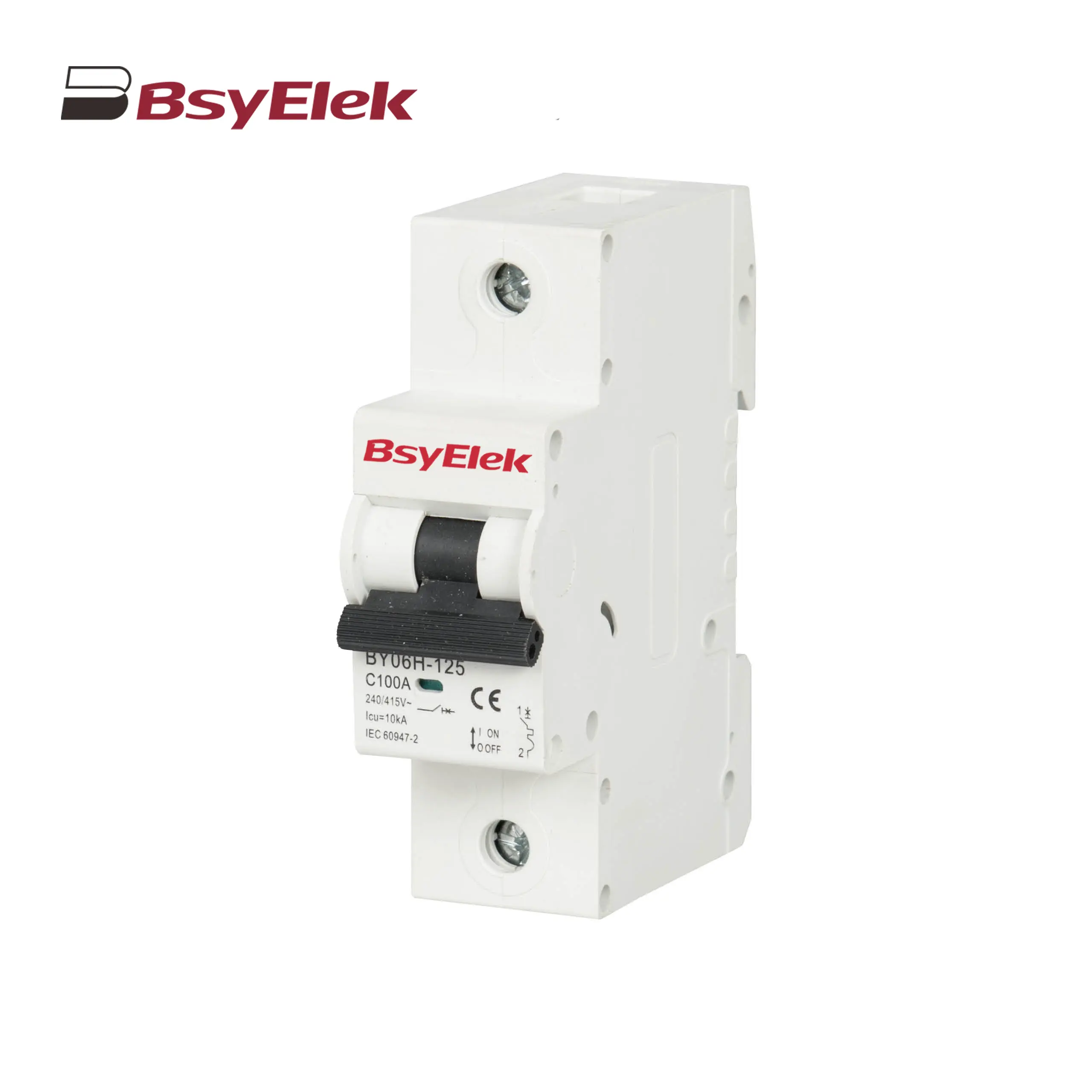
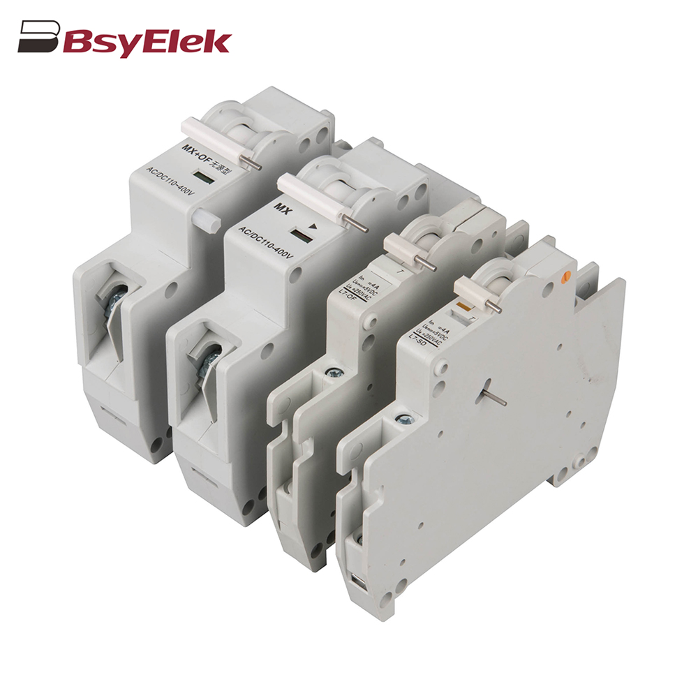
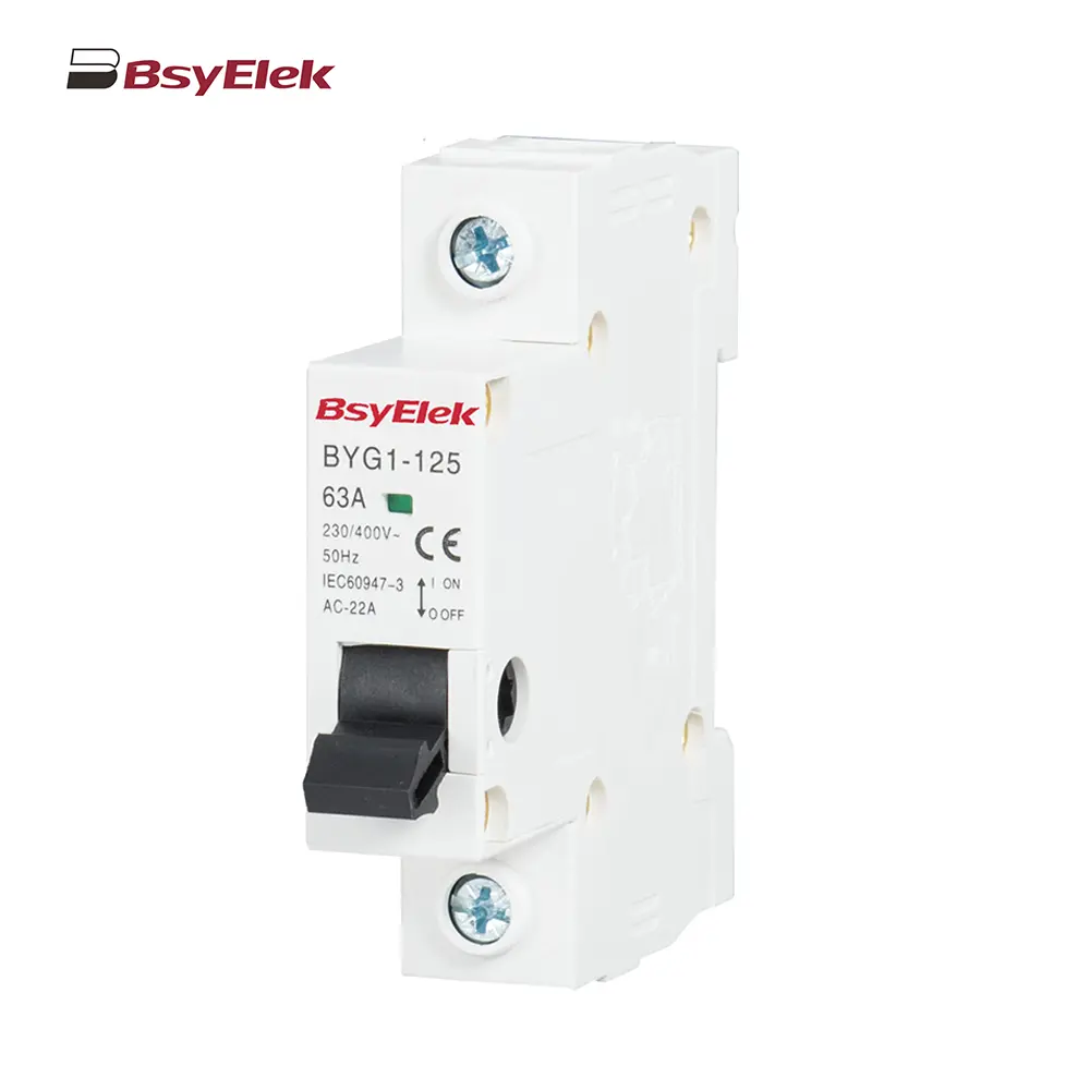
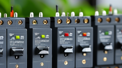
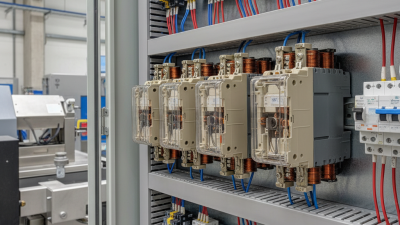
BY06H-125 MCB 10-15KA Miniature Circuit Breaker
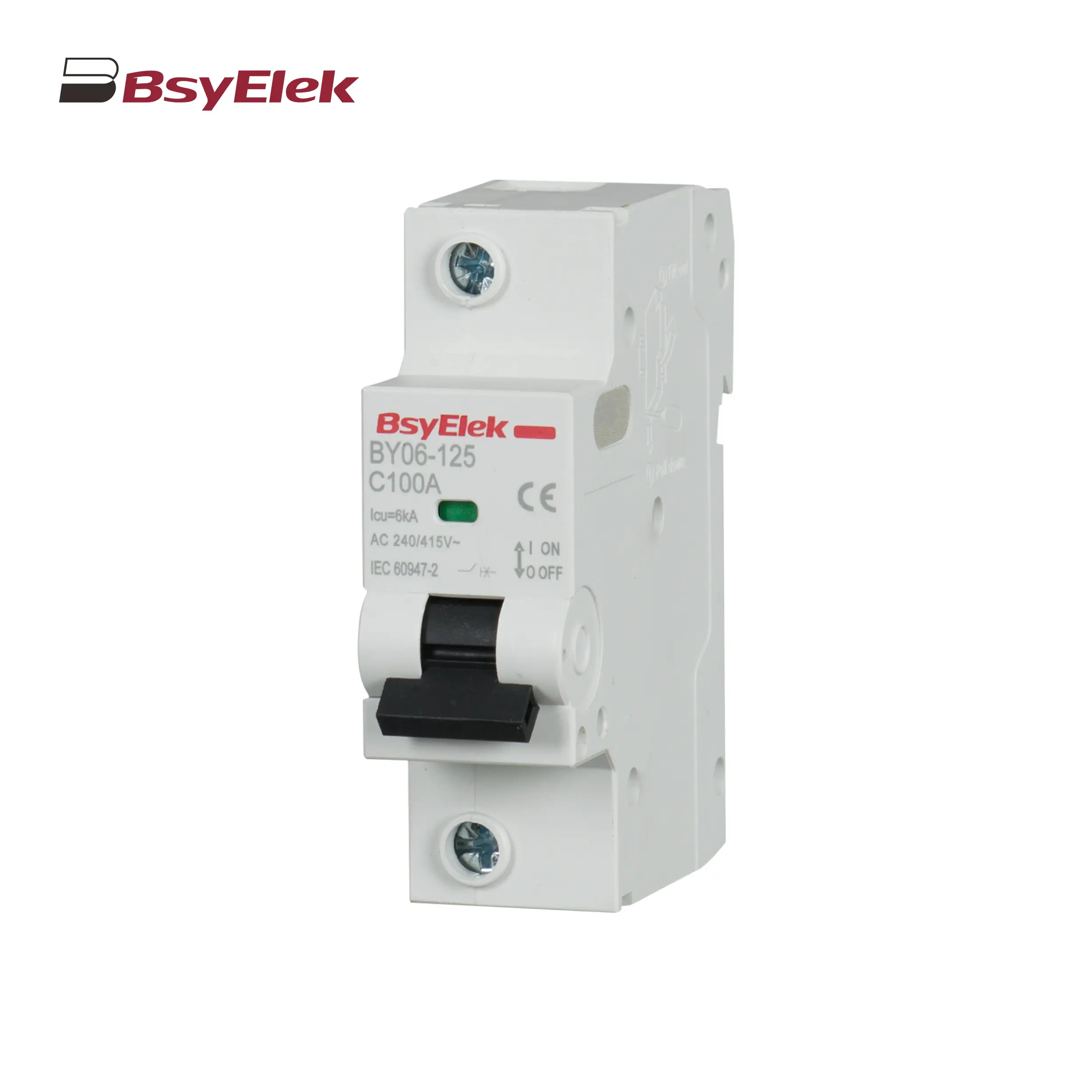
BY06-125 MCB 6KA Miniature Circuit Breaker
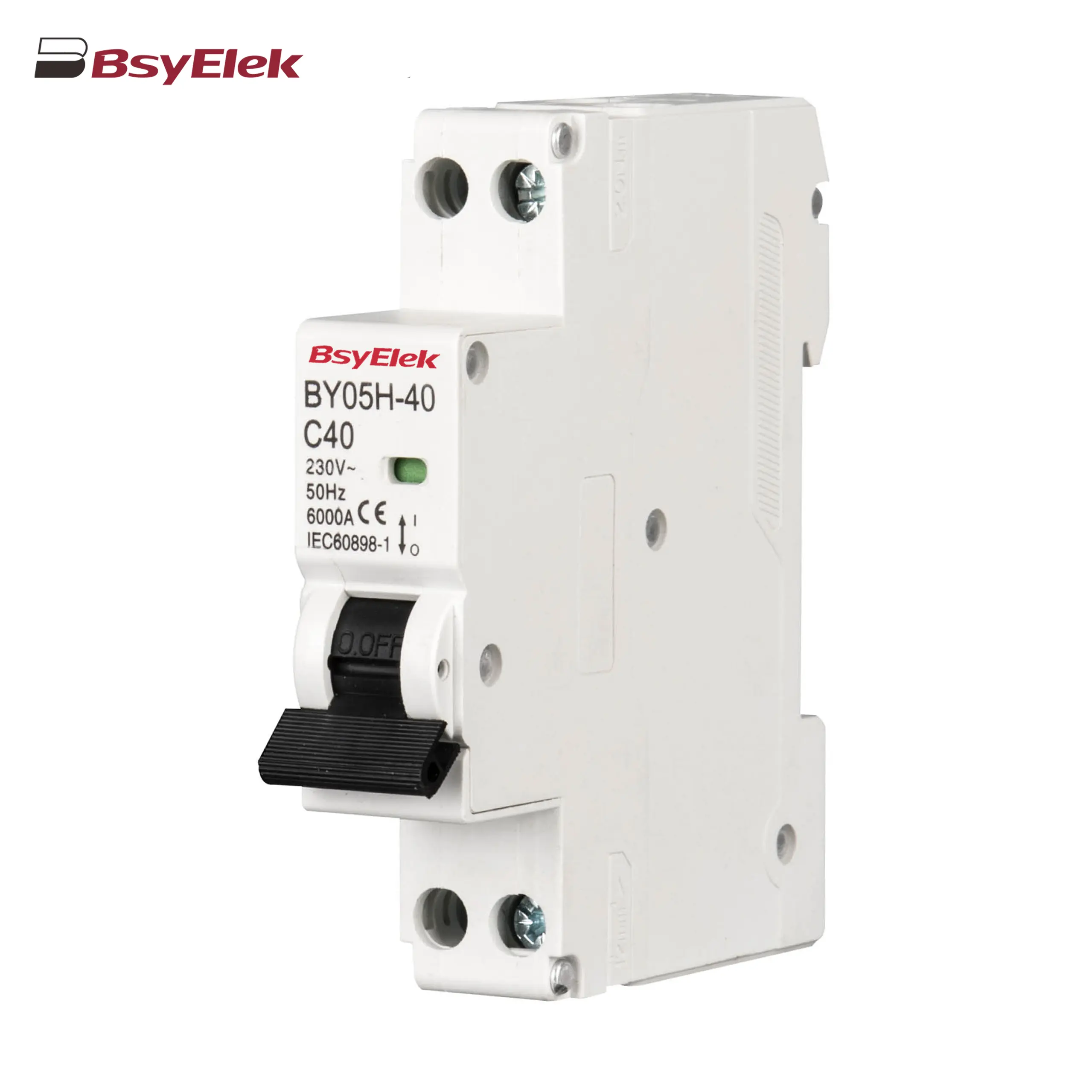
BY05H-40 MCB Single Modular 6KA Miniature Circuit Breaker
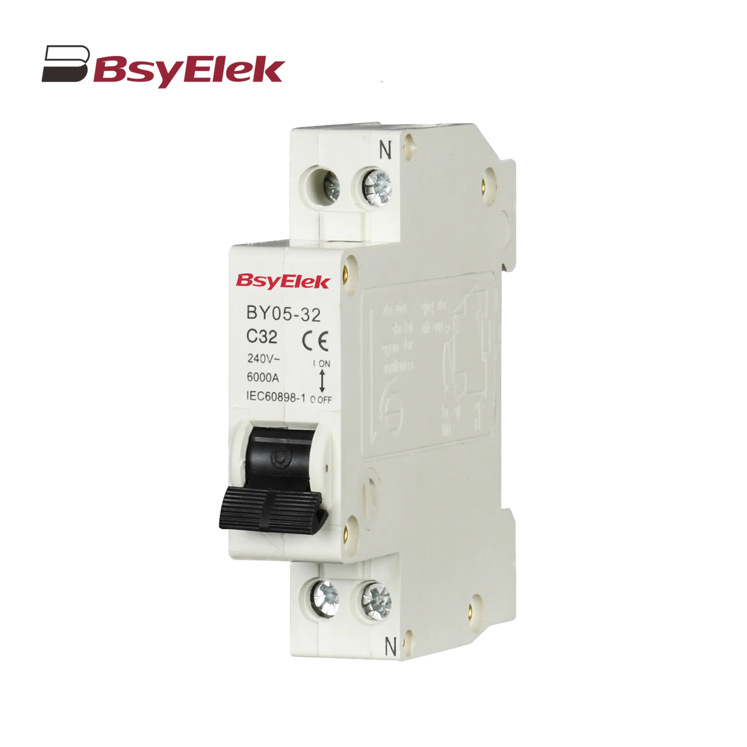
BY05-32 MCB Single Modular 3KA Miniature Circuit Breaker
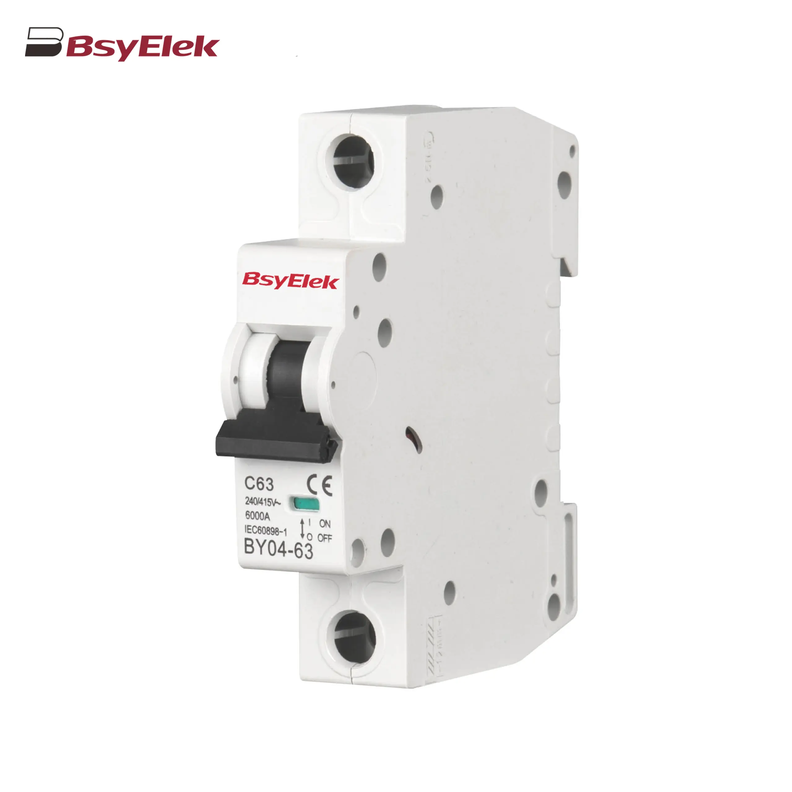
BY04-63 MCB 6-10KA Miniature Circuit Breaker
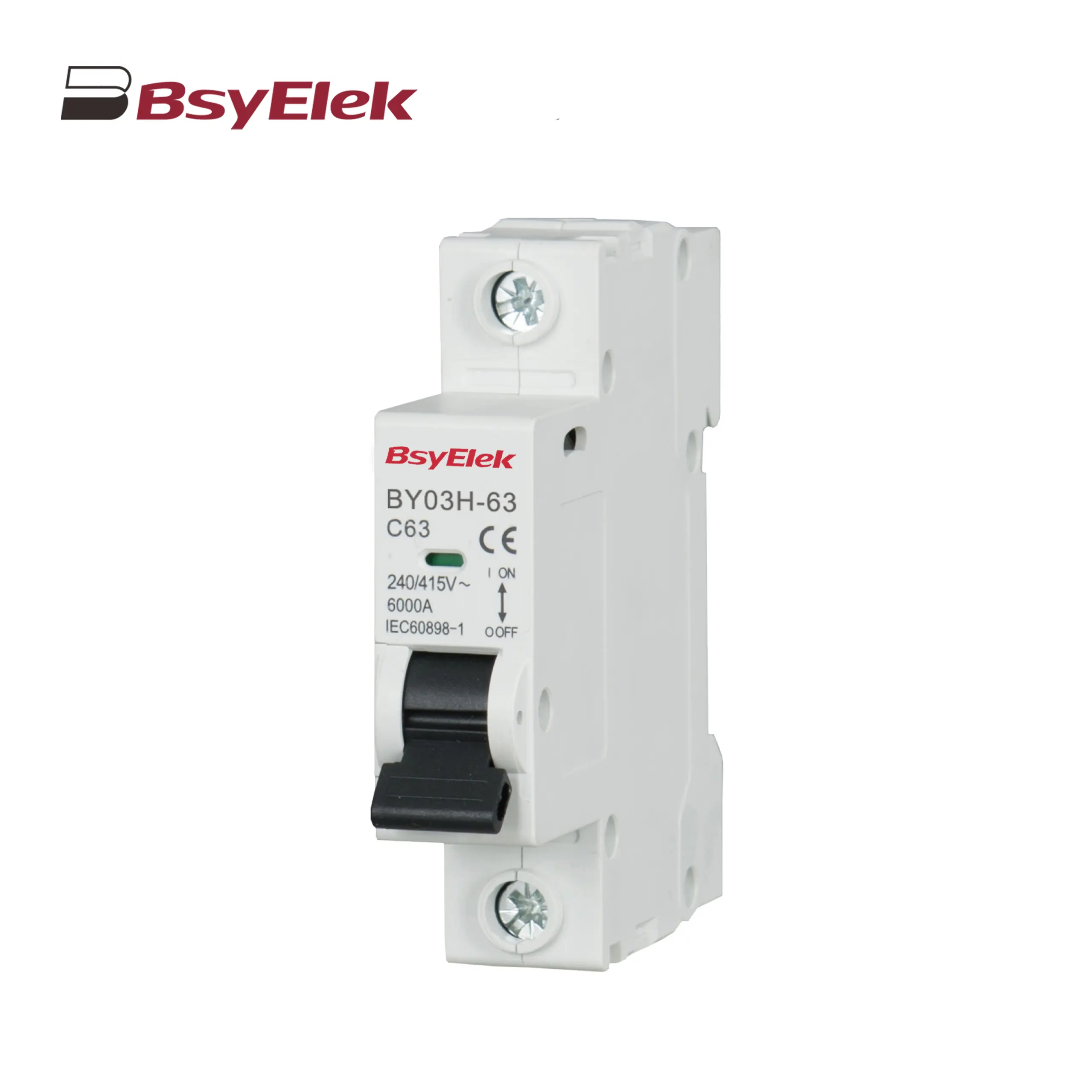
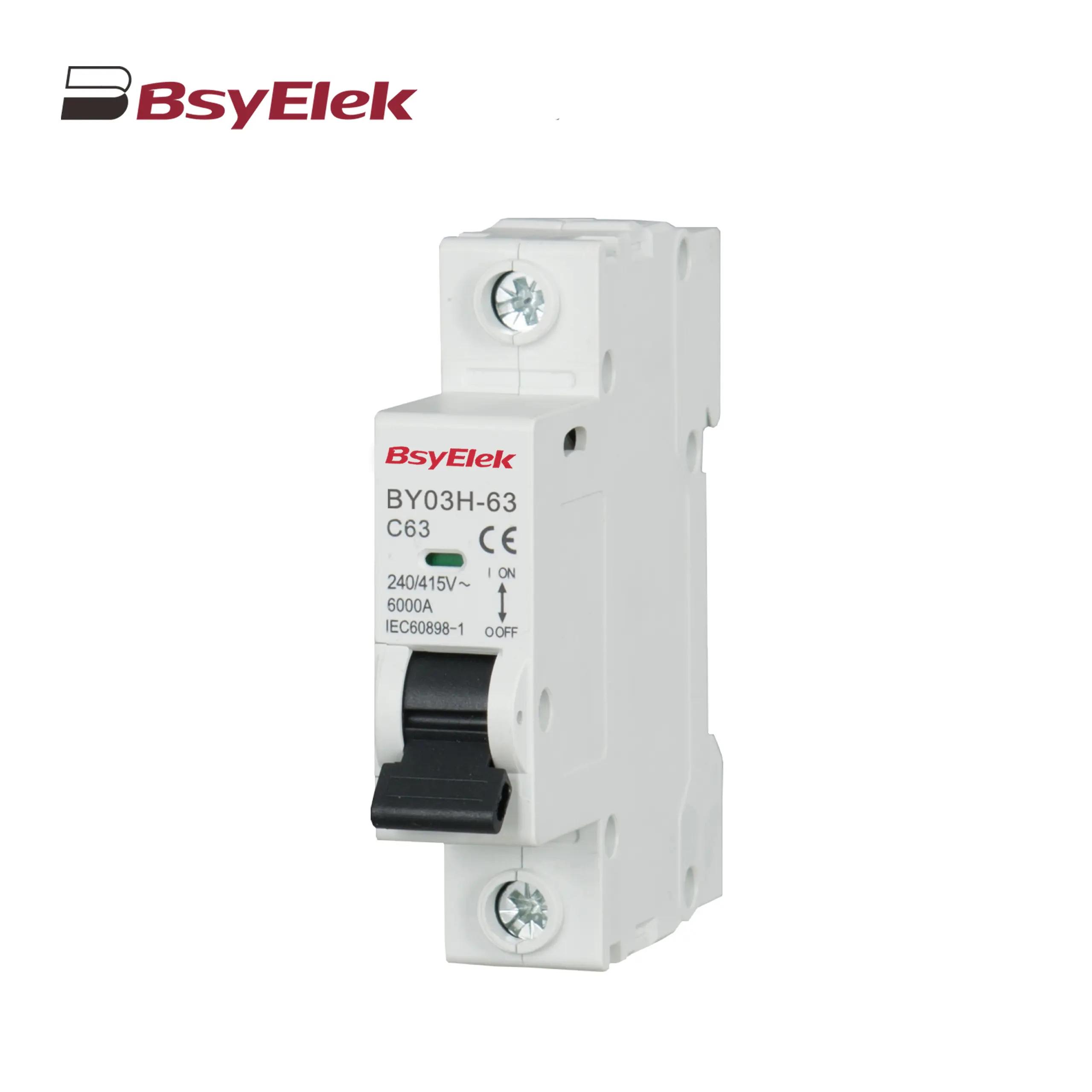
BY03H-63 MCB 6KA Miniature Circuit Breaker
BY03-63 MCB 4.5KA Miniature Circuit Breaker
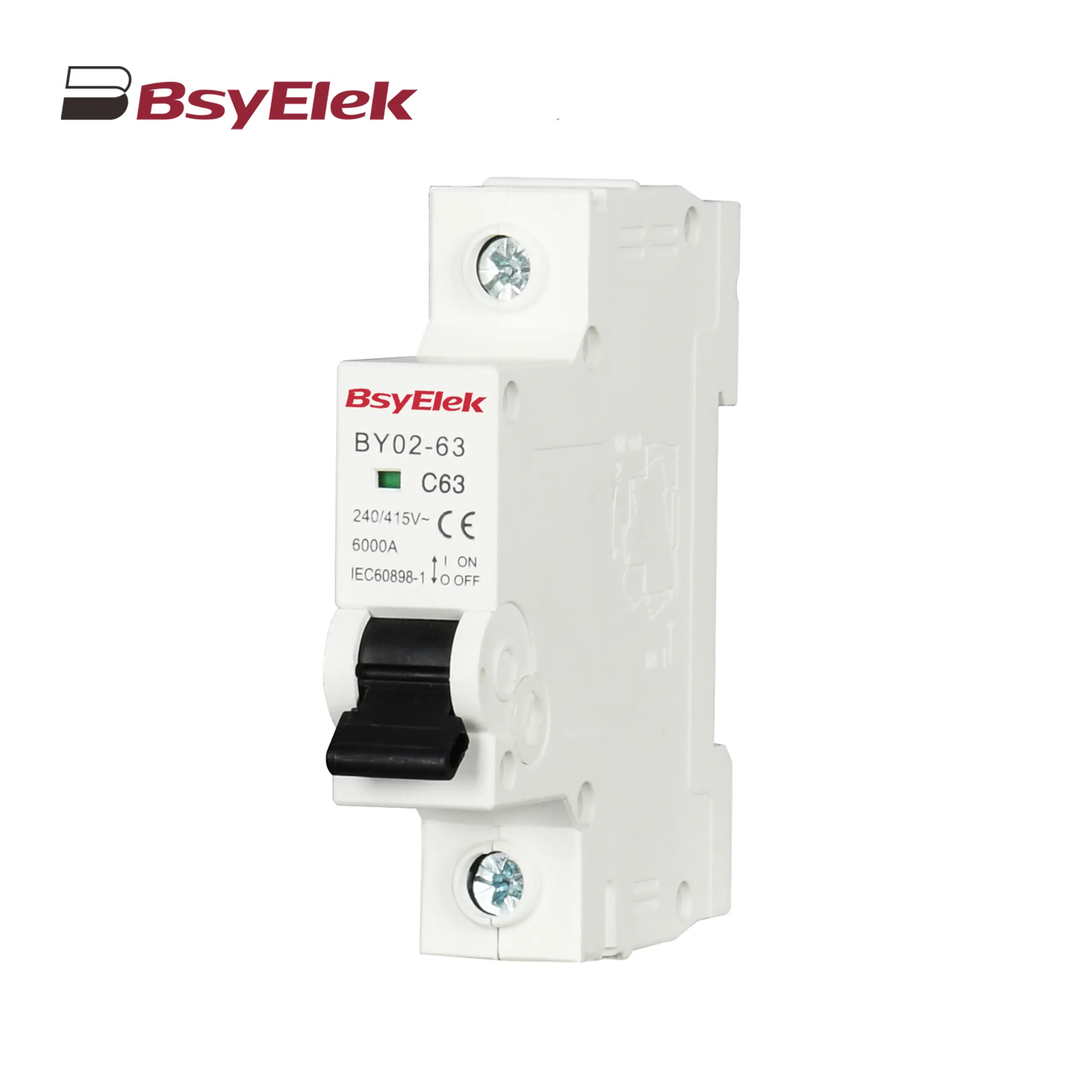
BY02-63 MCB 3kA Miniature Circuit Breaker
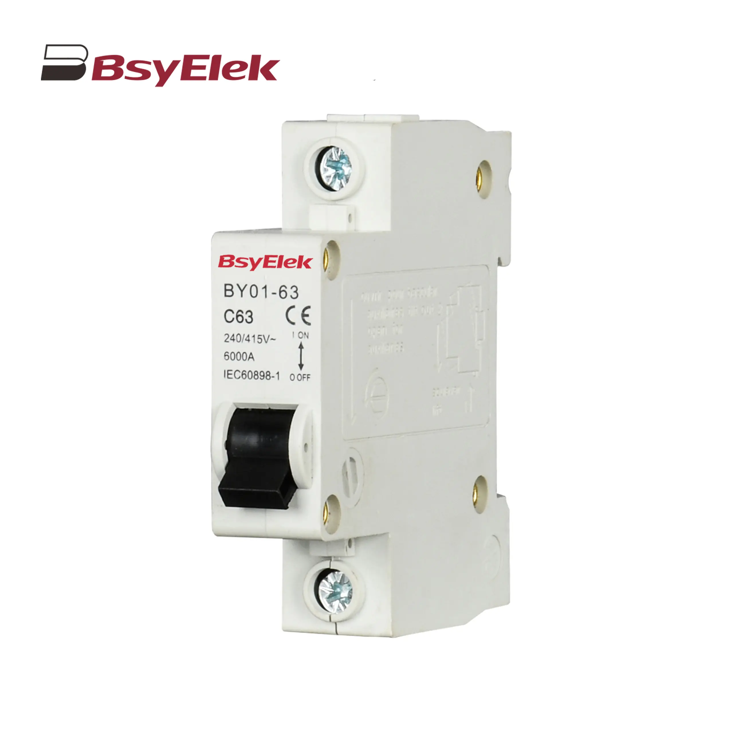
BY01-63 MCB 3kA Miniature Circuit Breaker
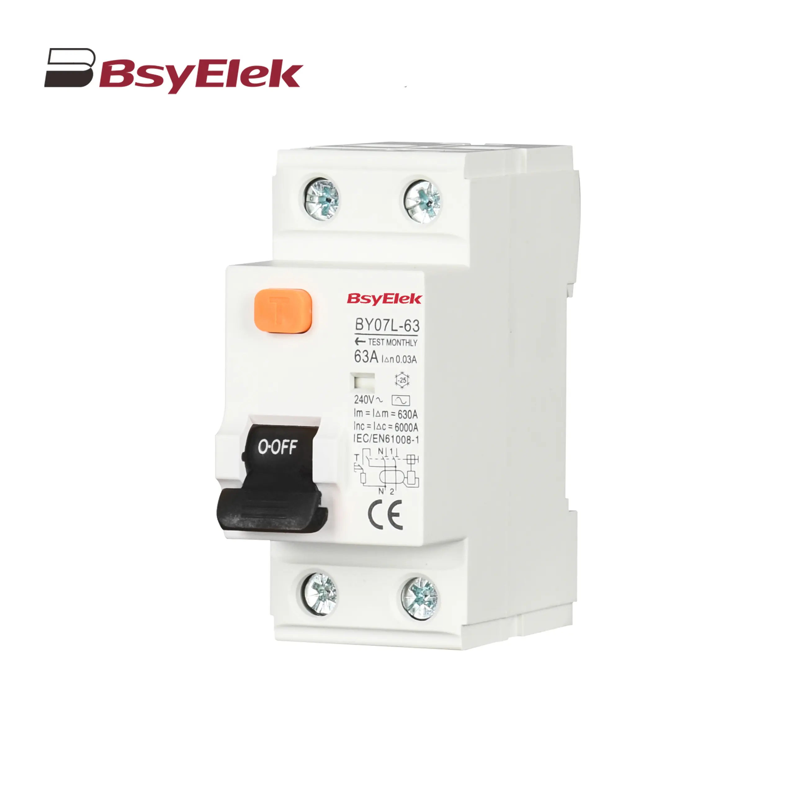
BY07L-63 RCCB 6KA Residual Current Circuit Breaker
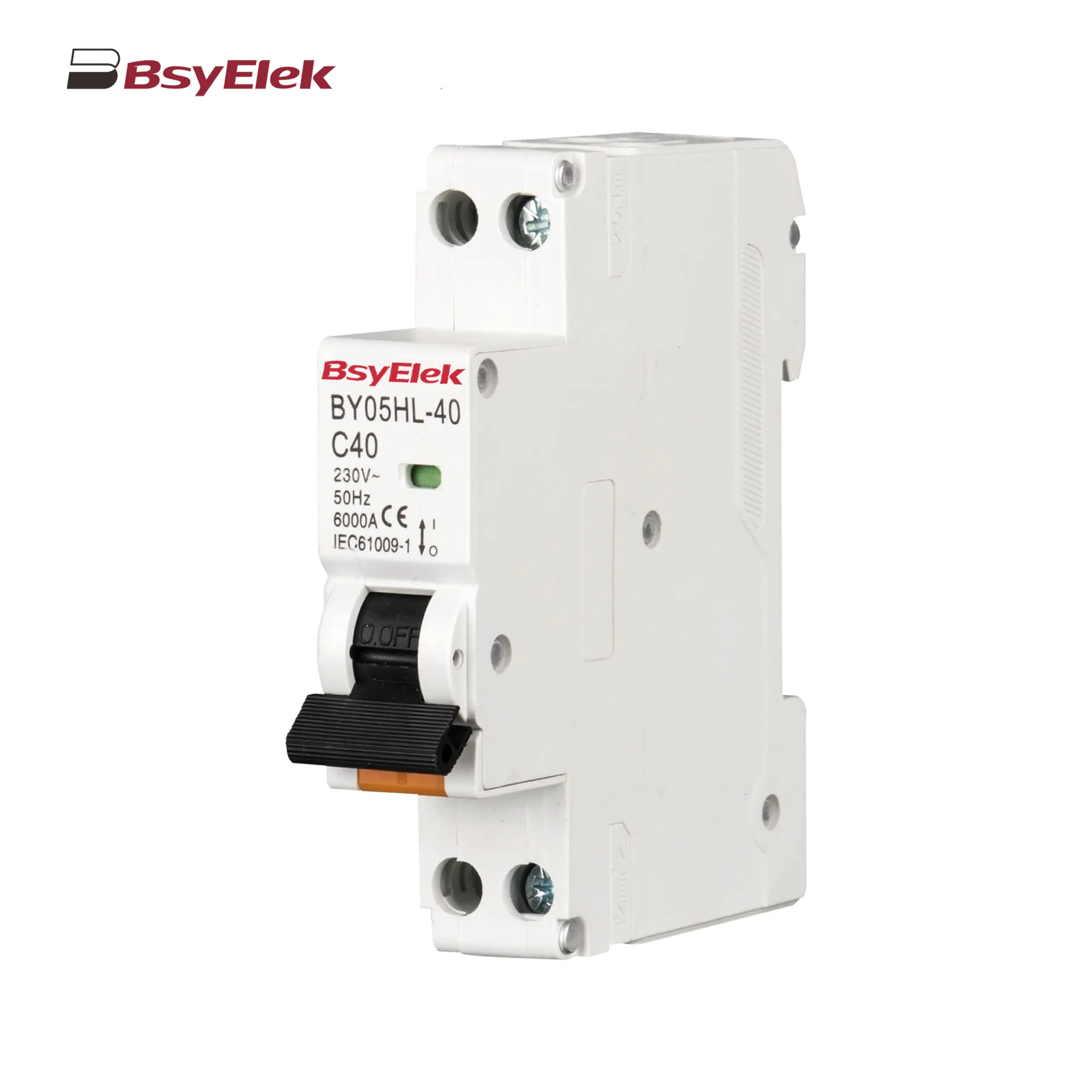
BY05HL-40 RCBO 6KA Residual Current Circuit Breaker with Over-current Protection
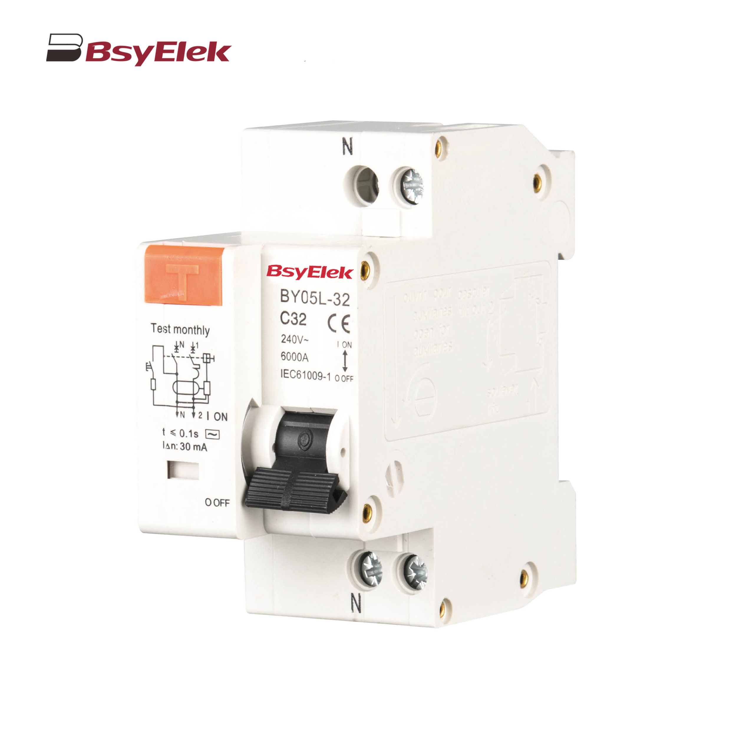
BY05L-32 RCBO 3KA Residual Current Circuit Breaker with Over-current Protection
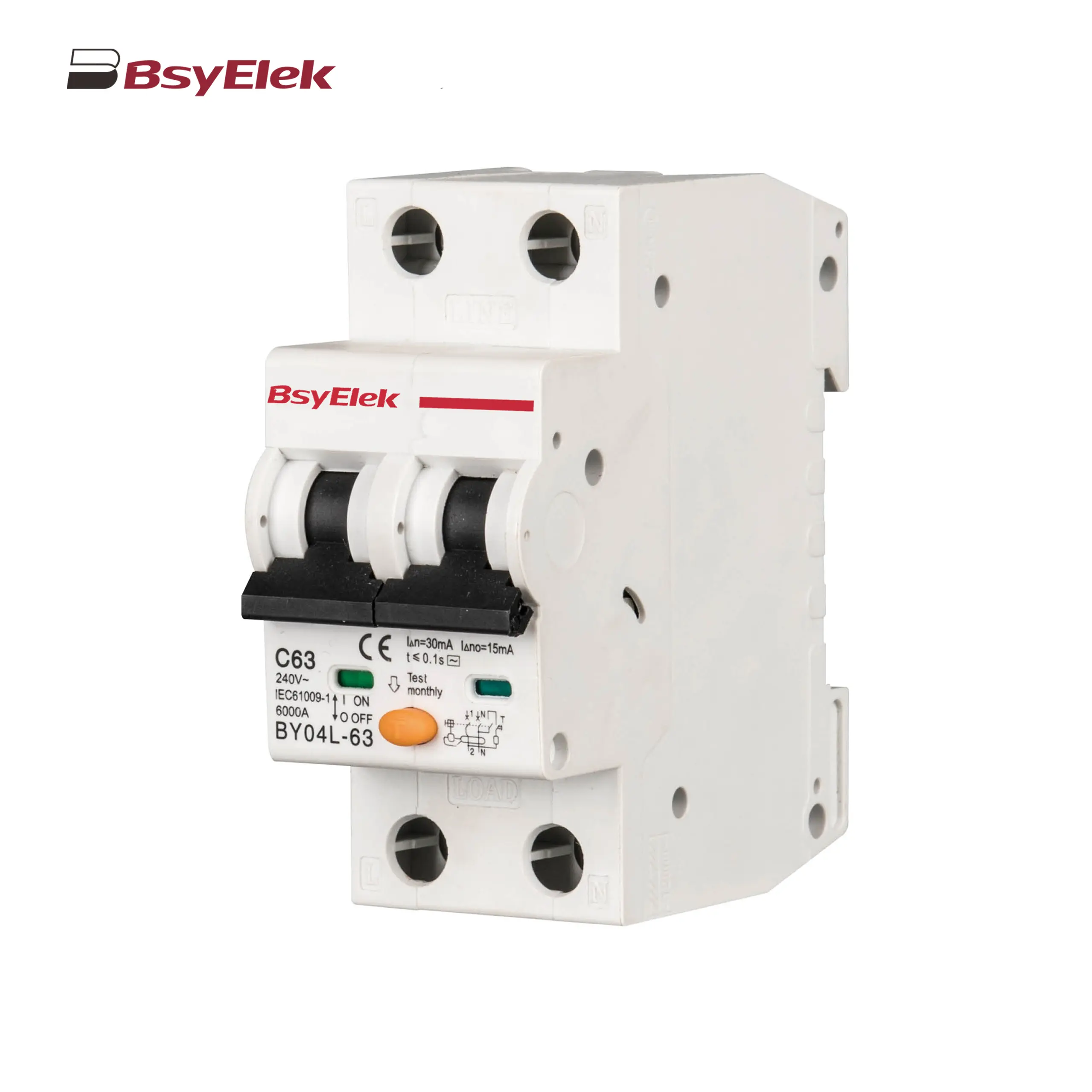
BY04L-63 RCBO 6KA Residual Current Circuit Breaker with Over-current Protection
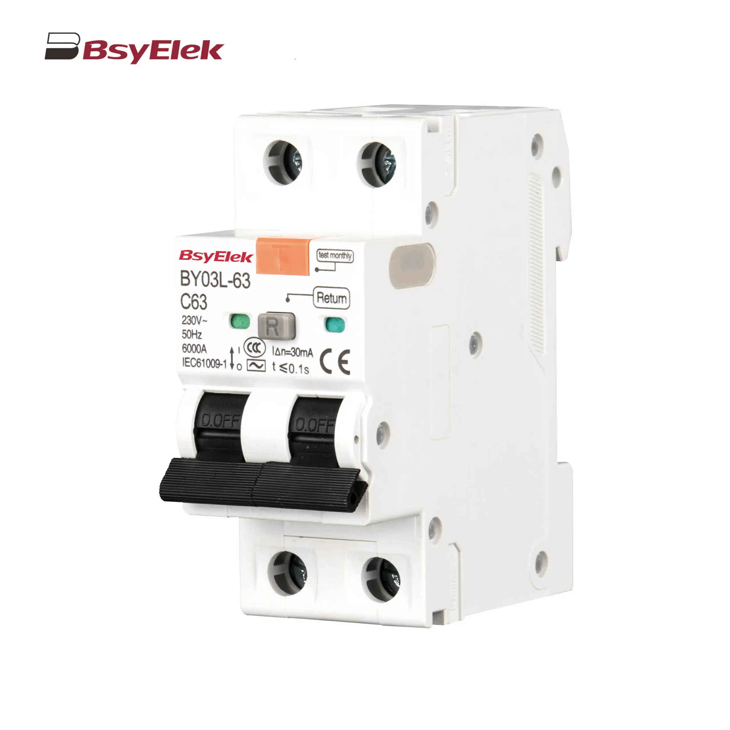
BY03L-63 RCBO 4.5KA Residual Current Circuit Breaker with Over-current Protection
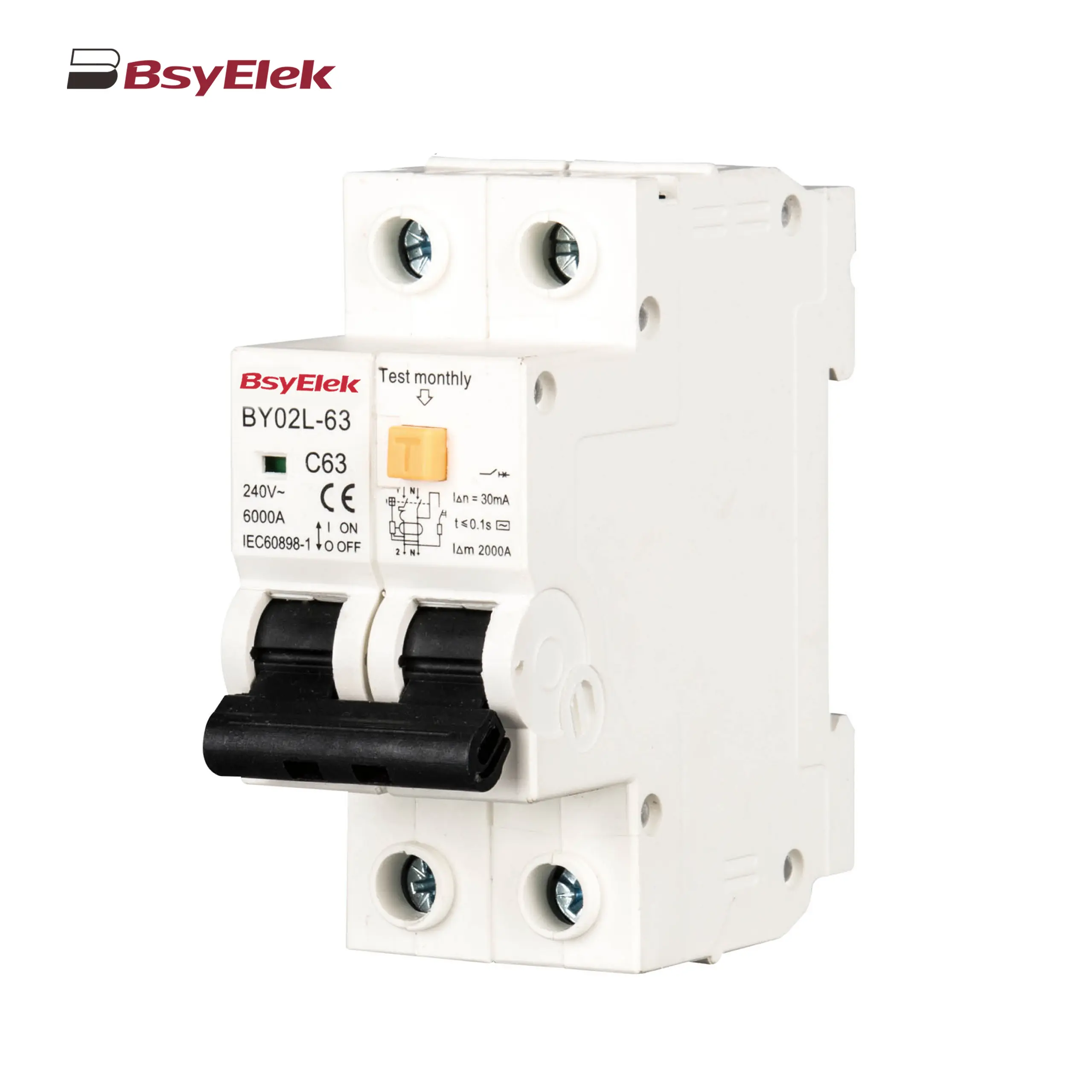
BY02L-63 RCBO 3KA Residual Current Circuit Breaker with Over-current Protection
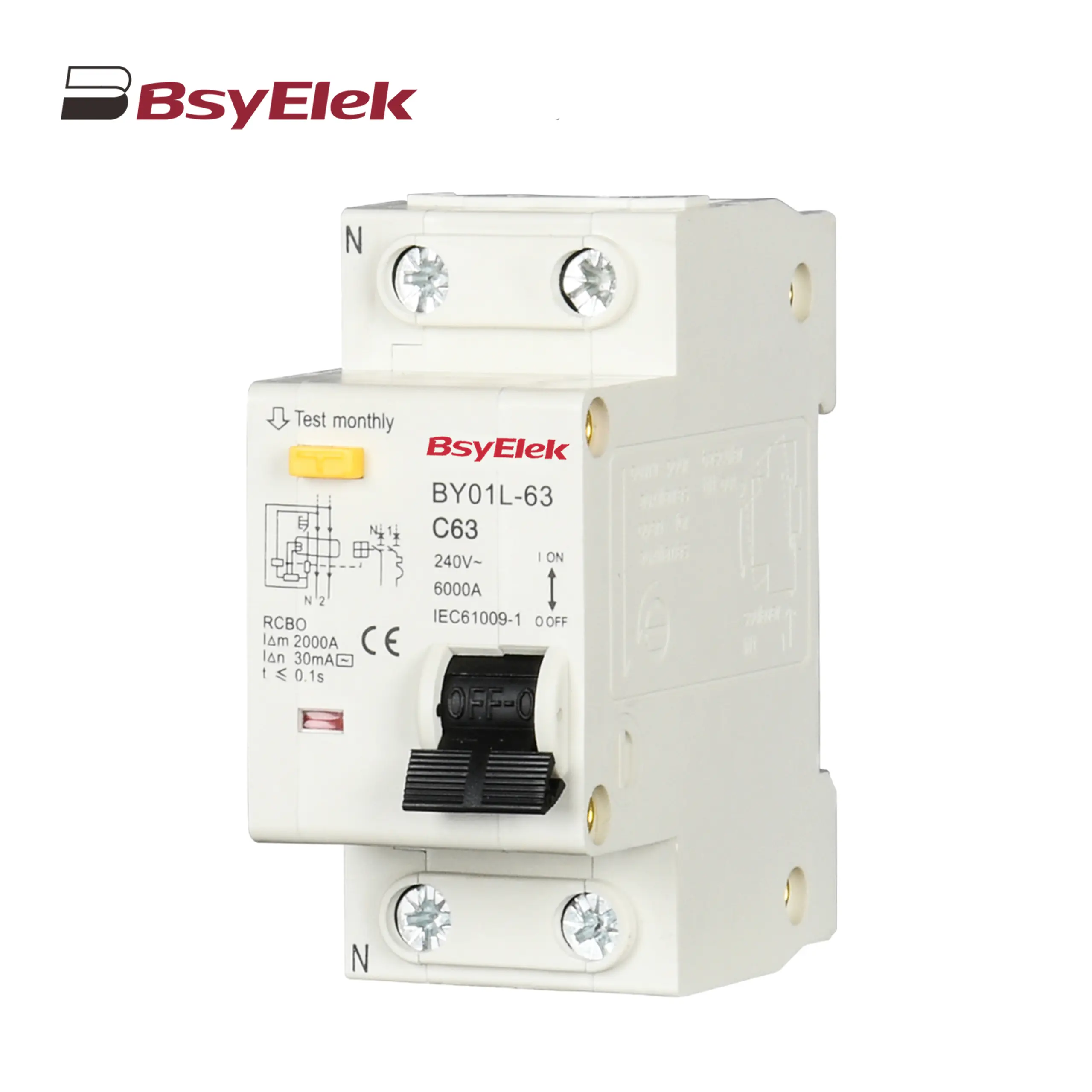
BY01L-63 RCBO 1P+N 3KA Residual Current Circuit Breaker with Over-current Protection
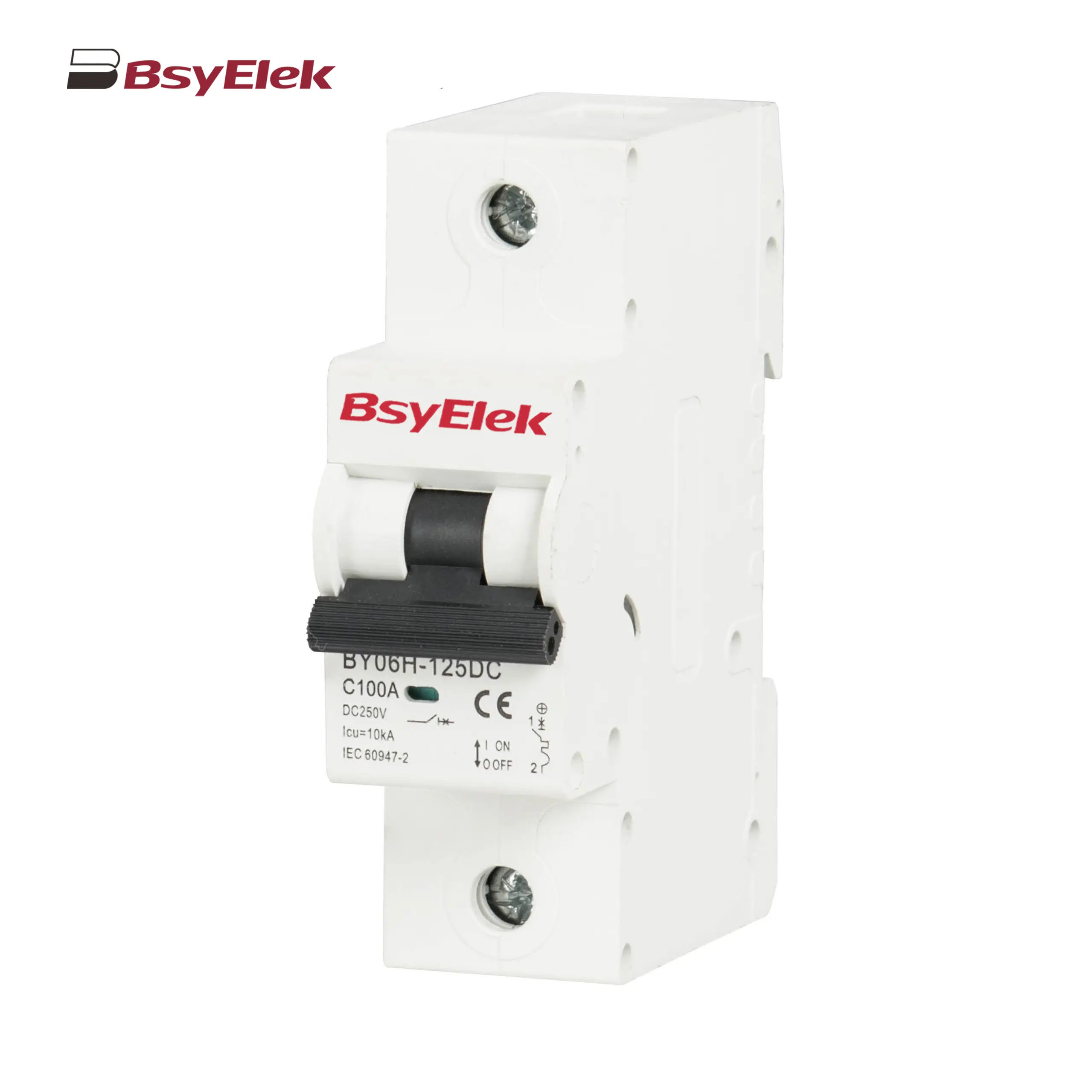
BY06H-125DC MCB 10-15kA DC Miniature Circuit Breaker
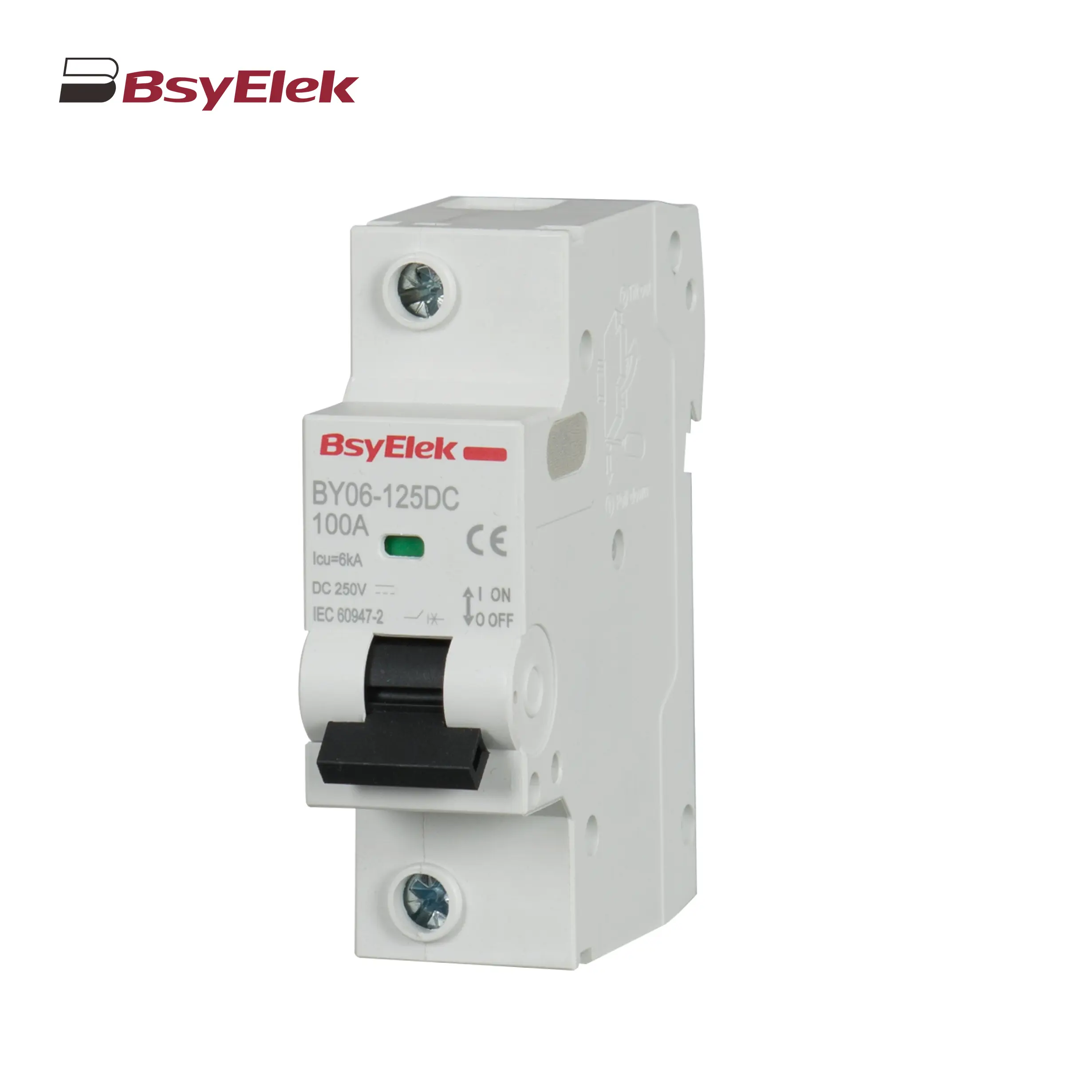
BY06-125DC MCB 6kA DC Miniature Circuit Breaker
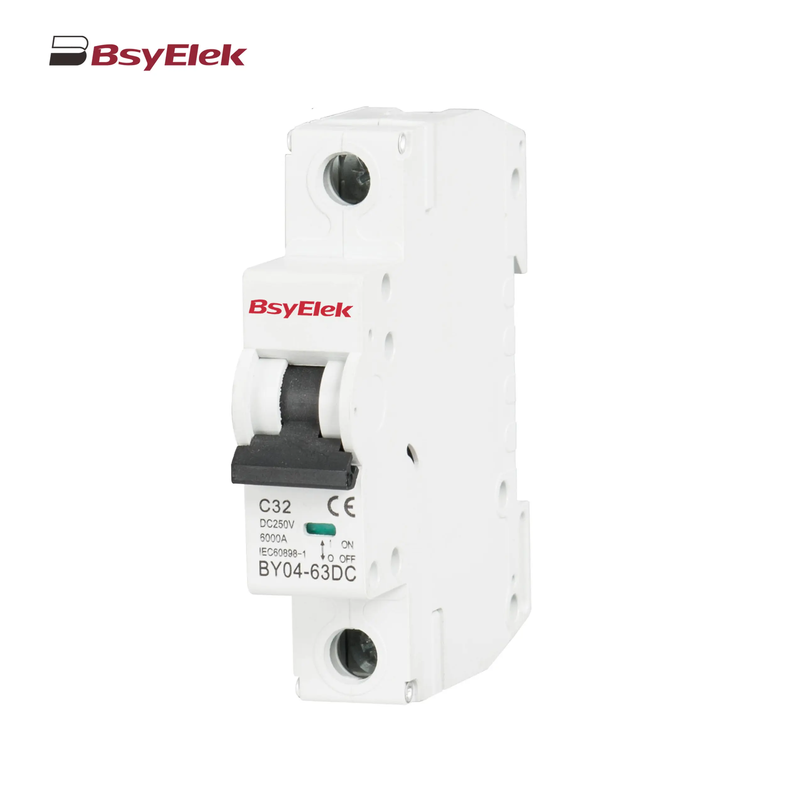
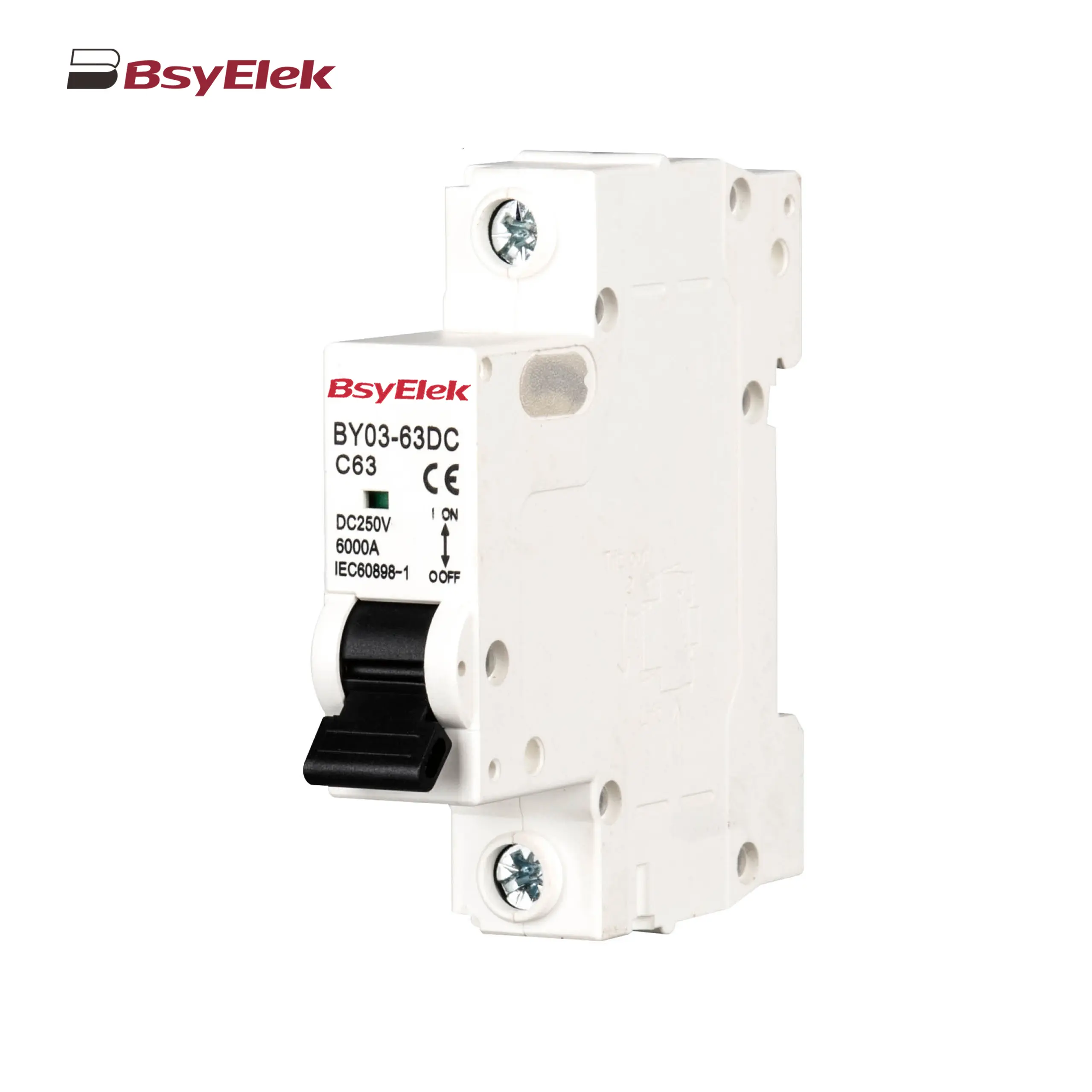
BY04-63DC MCB 6-10kA DC Miniature Circuit Breaker
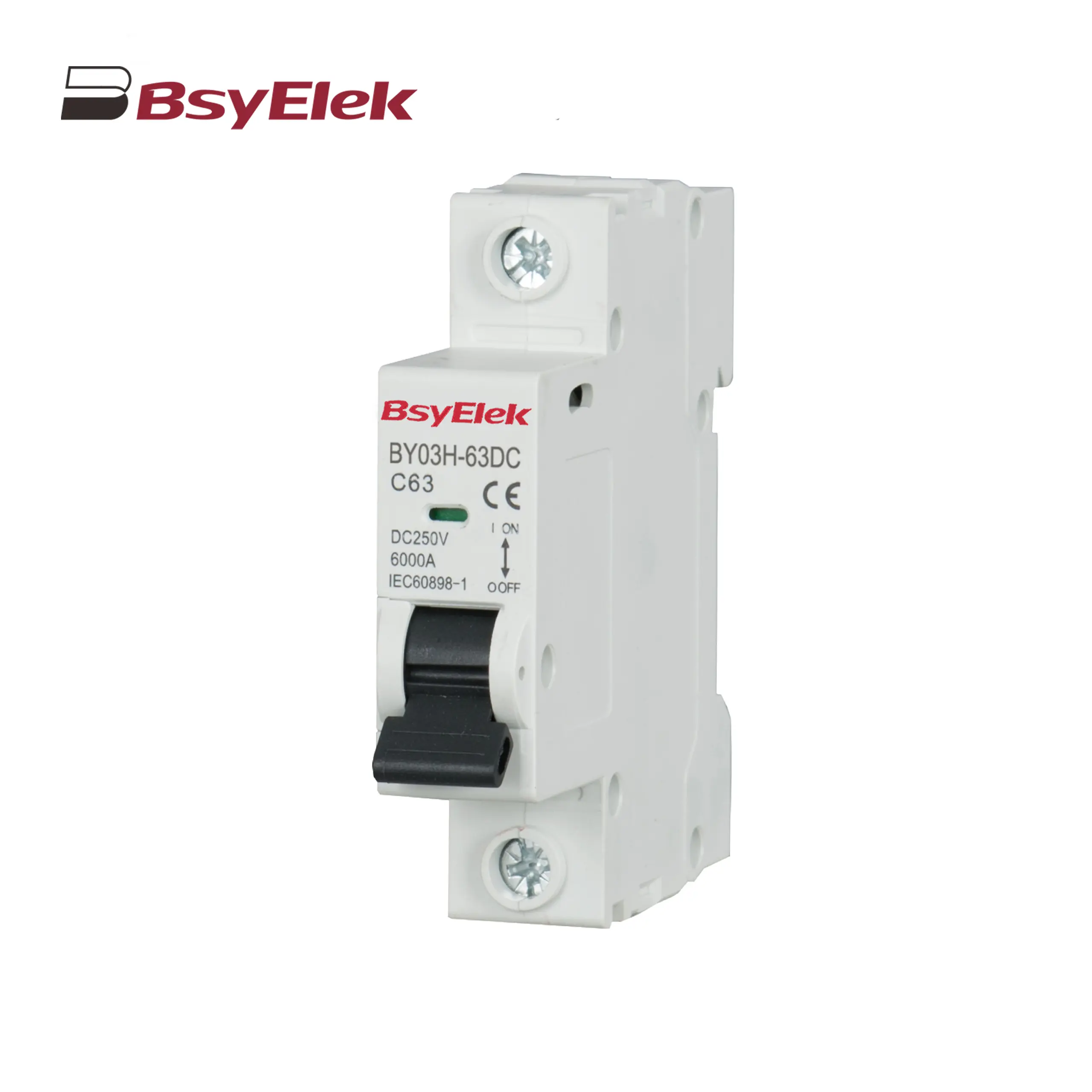
BY03H-63DC MCB 6kA DC Miniature Circuit Breaker
BY03-63DC MCB 4.5kA DC Miniature Circuit Breaker
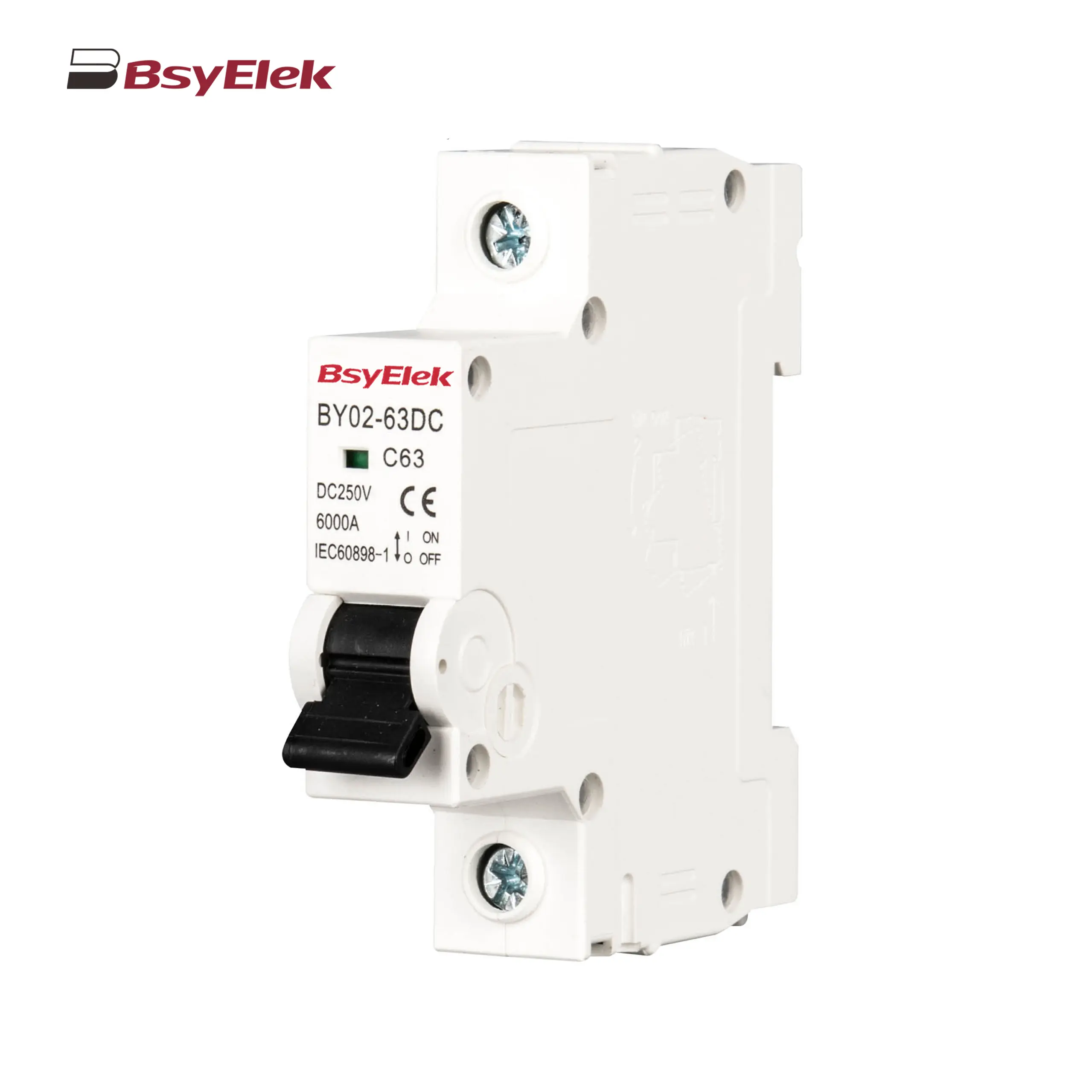
BY02-63DC MCB 3kA DC Miniature Circuit Breaker
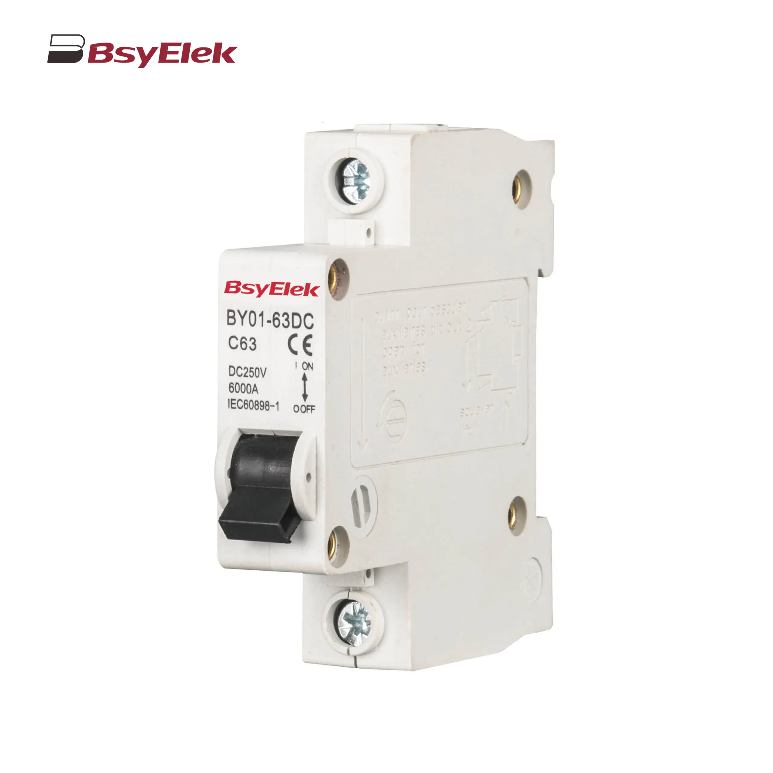
BY01-63DC MCB 3kA DC Miniature Circuit Breaker
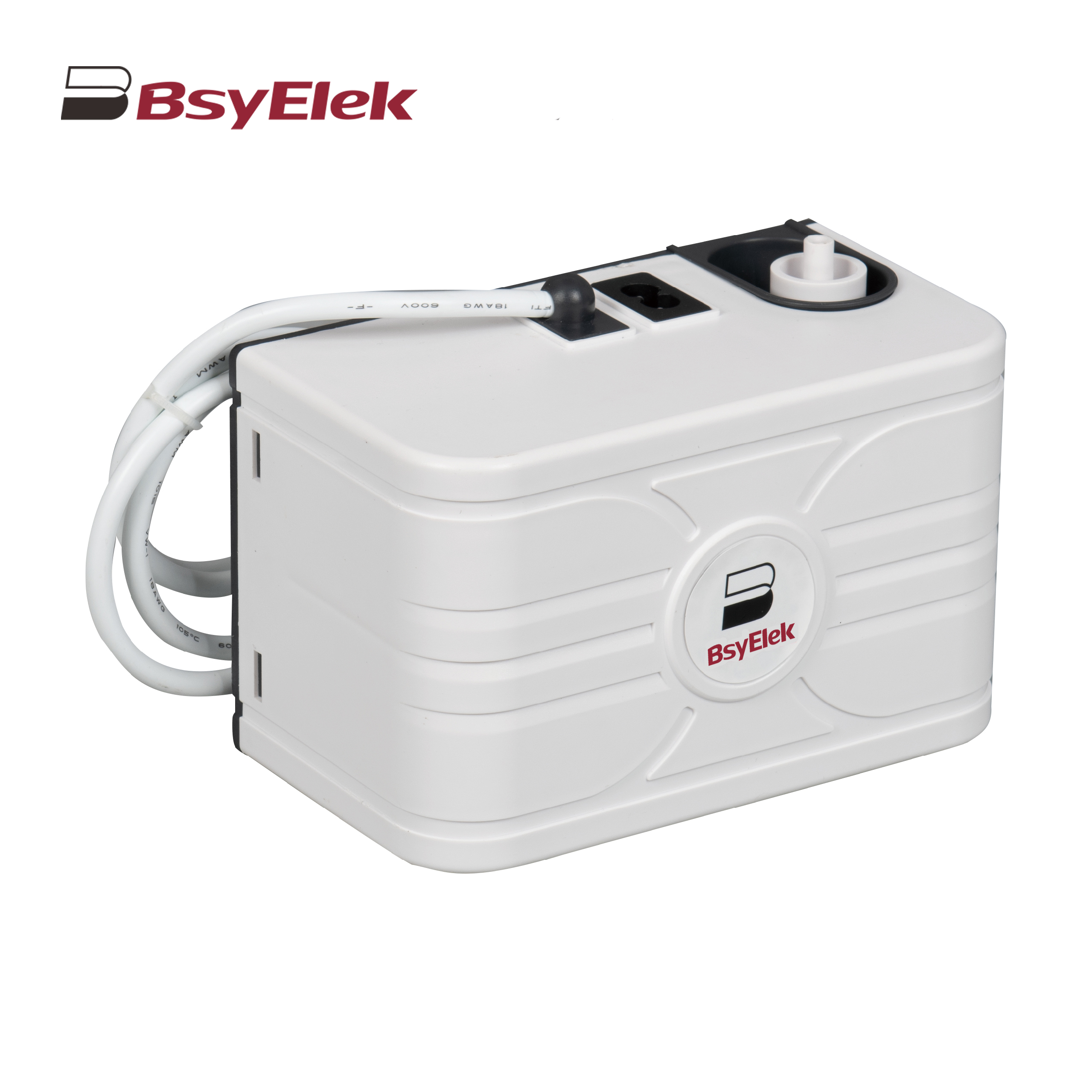
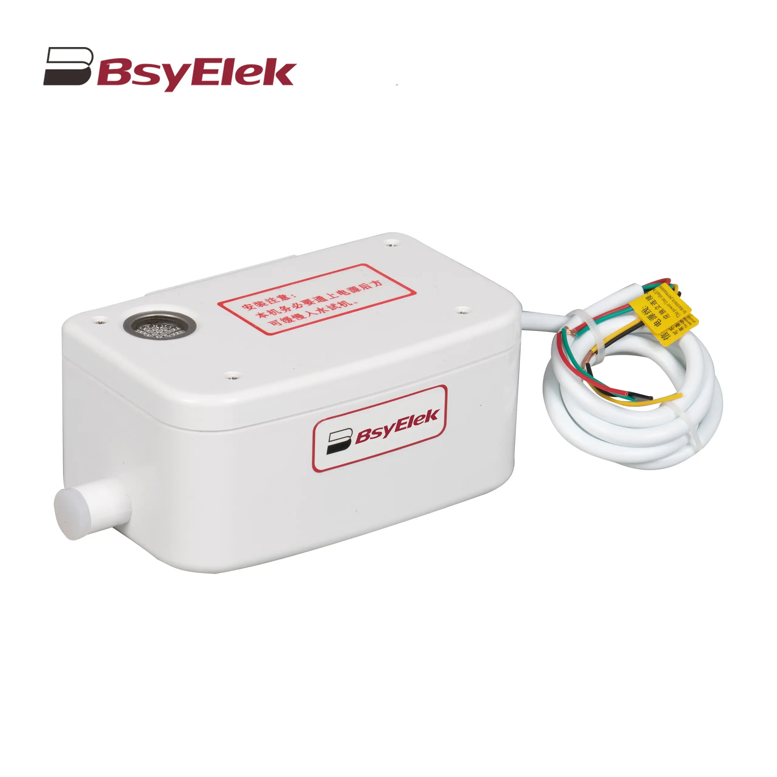
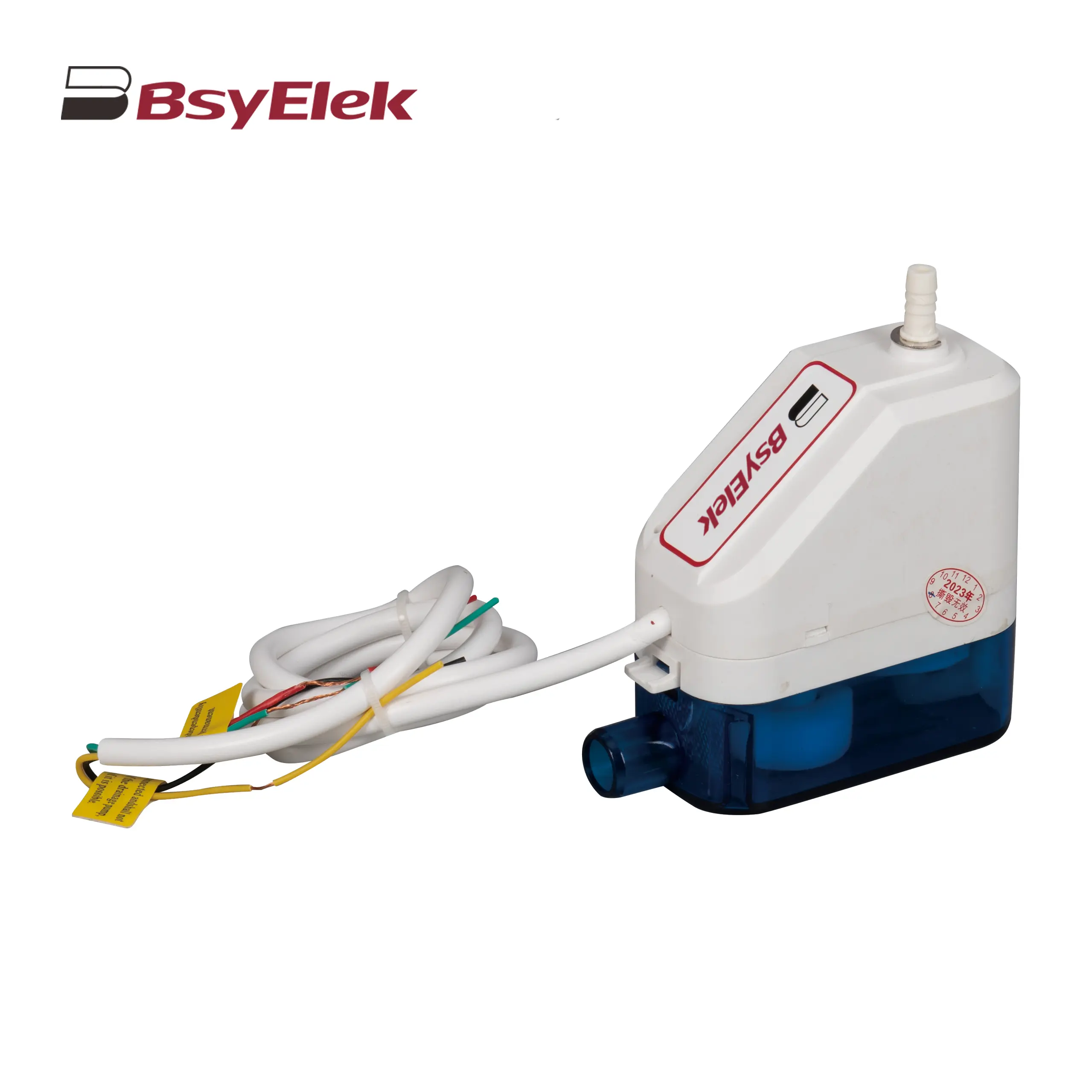
BY-5018 1.8M Engineering Drainage Pump
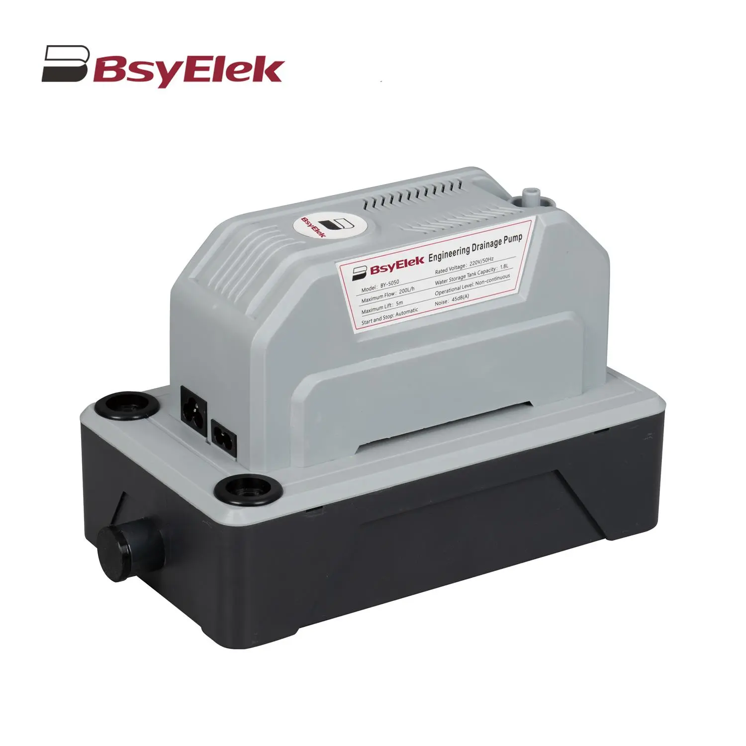
BY-5050 5M Engineering Drainage Pump
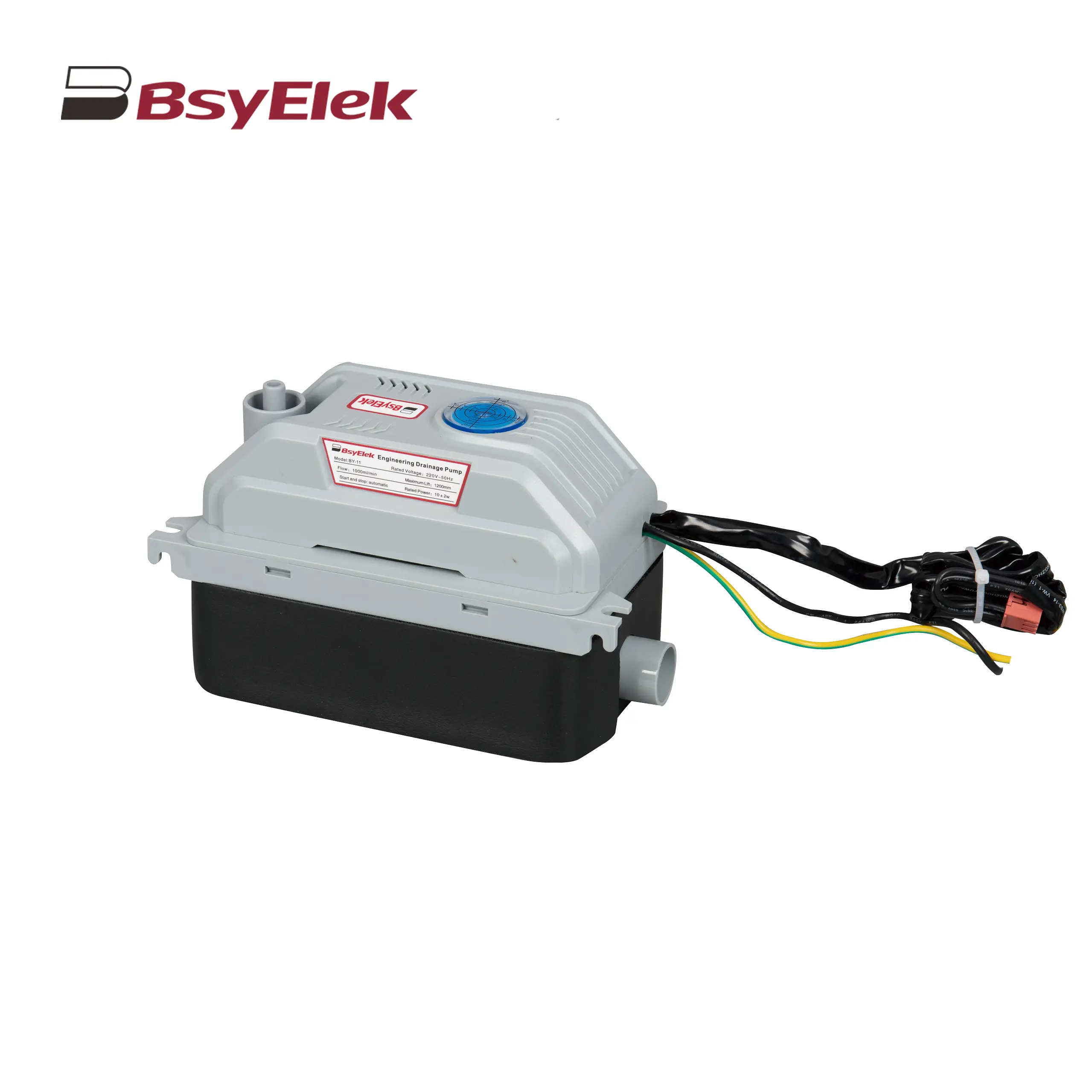
BY-11 1.2M Engineering Drainage Pump
SBH-05 0.7M Original Drainage Pump of Duct Type Air Conditioner
BY-24A/40A 10M Drainage Pump of Air Conditioner
BY-50A 12M Drainage Pump of Air Conditioner
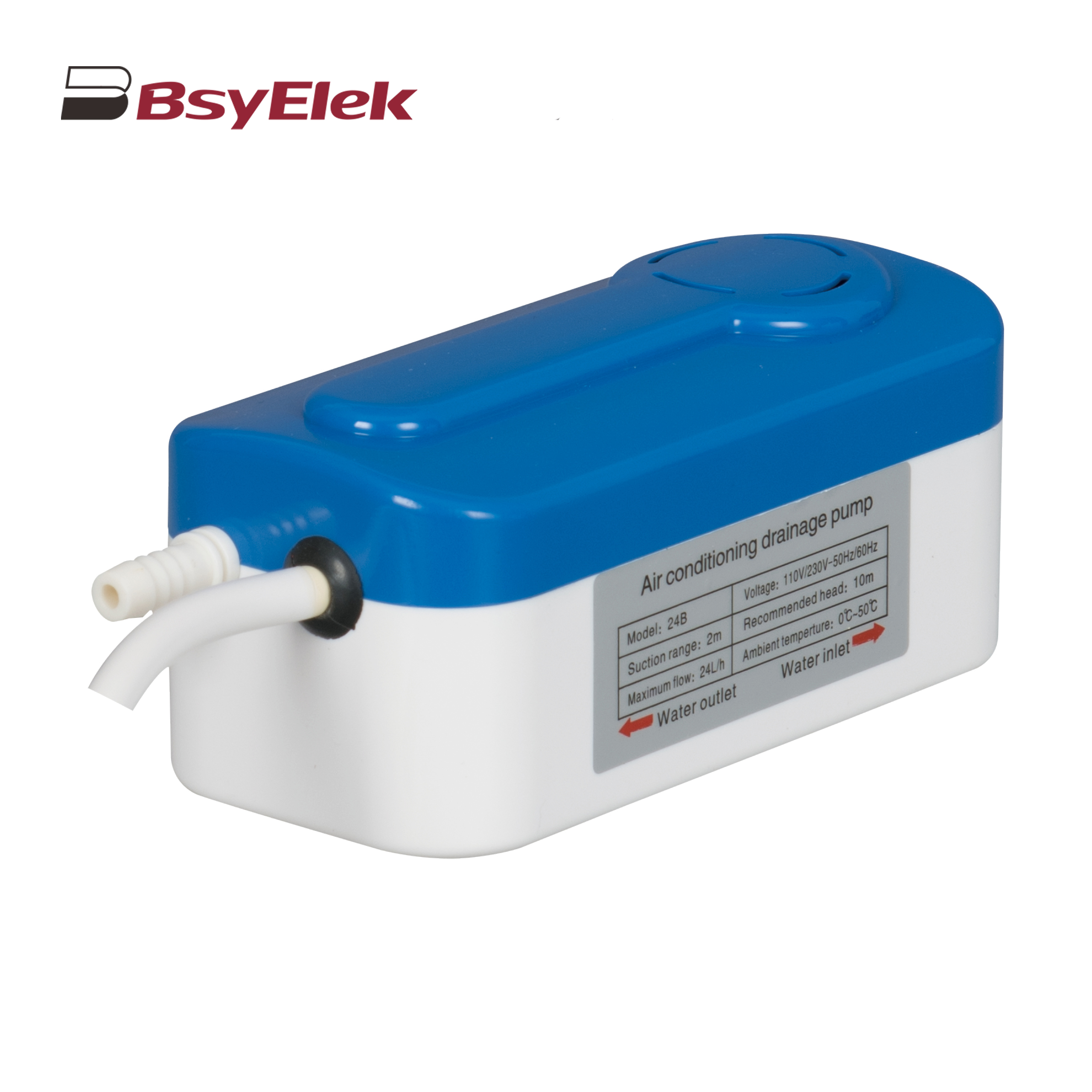
BY-24B/40B 10M Split Type Drainage Pump
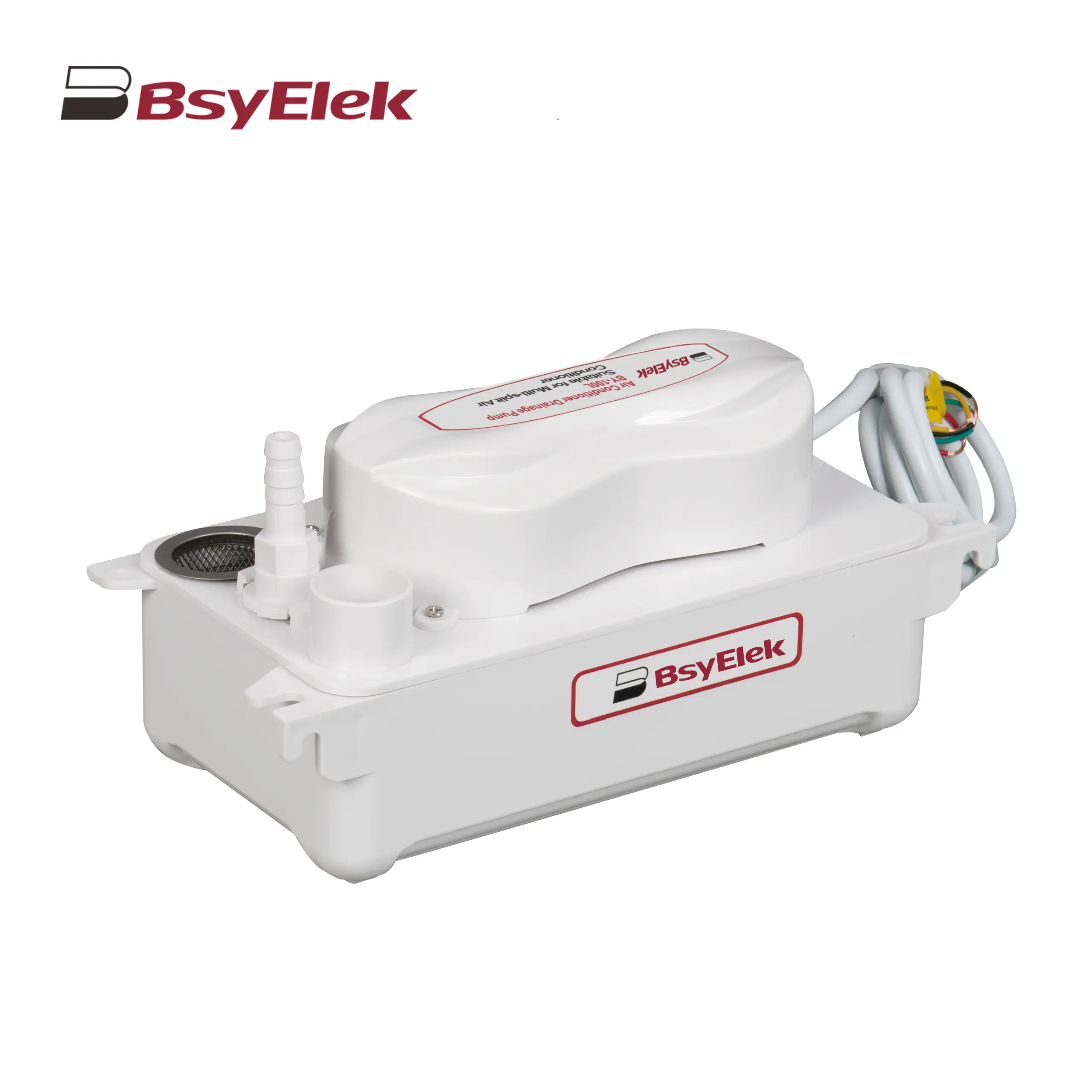
BY-100L 2M Drainage Pump of Air Conditioner
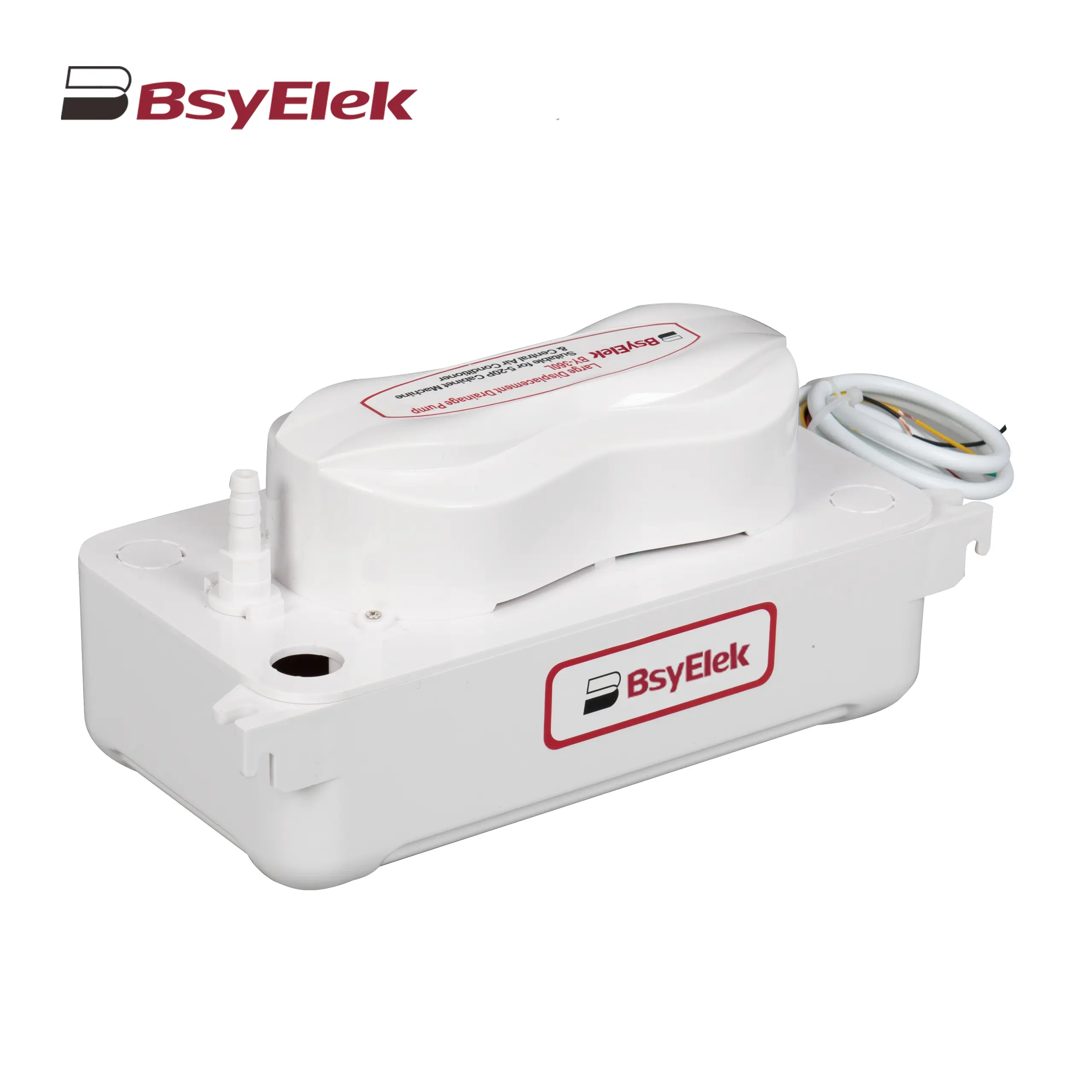
BY-360L 6M Large Displacement Drainage Pump
BY-24C/40C 10M Corner Drainage Pump
Choosing a Dc Surge Protector for solar panels starts with the array’s actual electrical limits, not a product label alone. A device rated for the wrong voltage may fail to protect equipment—or may not operate as intended. As a paraphrase of surge-protection expert Peter Hasse’s published work: protection should be coordinated with the system it serves. That principle matters on a roof, where long cable runs can carry a transient toward an inverter in seconds.
Check the array’s maximum open-circuit voltage, including the increase caused by low temperatures. The protector’s maximum continuous operating voltage must suit that figure. Then examine its protection level, discharge-current rating, and short-circuit current rating. Small details matter. A few extra metres of conductor can reduce protection performance, so installation location and lead length deserve attention. The correct device also depends on the system design and whether external lightning protection is present.
A label is not enough. Review the manufacturer’s technical data and installation instructions, and confirm the device is intended for photovoltaic DC circuits. Look for a clear status indicator and a practical replacement process after a surge. This choice can feel overly technical. It is. Still, a careful check of voltage, grounding, and wiring can prevent a costly mismatch. The outline that follows explains these selection points, common errors, and the questions to ask before installation. Not every array is the same, and a quick rule may miss an important detail.
Solar-panel DC circuits can face surges even when lightning does not strike a module. A nearby strike may induce voltage in long rooftop cables. Those cables can span exposed roof sections before reaching the inverter. Switching equipment can also create brief transients. Not just during storms. DC current can sustain an arc, so protection must suit the circuit’s actual voltage and layout. It is easy to overlook cable routing when assessing risk.
Choose a surge protective device designed for photovoltaic DC circuits. Check that its maximum continuous operating voltage matches the array’s maximum open-circuit voltage, including the increase possible in cold weather. An AC-rated device is not a substitute. The grounding arrangement matters, too. Review the system diagram and device specifications, or ask a qualified solar electrician to verify compatibility. Keep connecting leads short and follow the installation instructions; long leads can reduce protection effectiveness.
Tips: Consider where cables enter the building and where sensitive equipment sits. Protection may be needed at more than one point, depending on cable runs and system design. Inspect the device’s status indicator during routine maintenance. A green light is useful, but it does not prove every connection is sound. Check connections and grounding as well.
| Selection factor | What to check | Practical guidance |
|---|---|---|
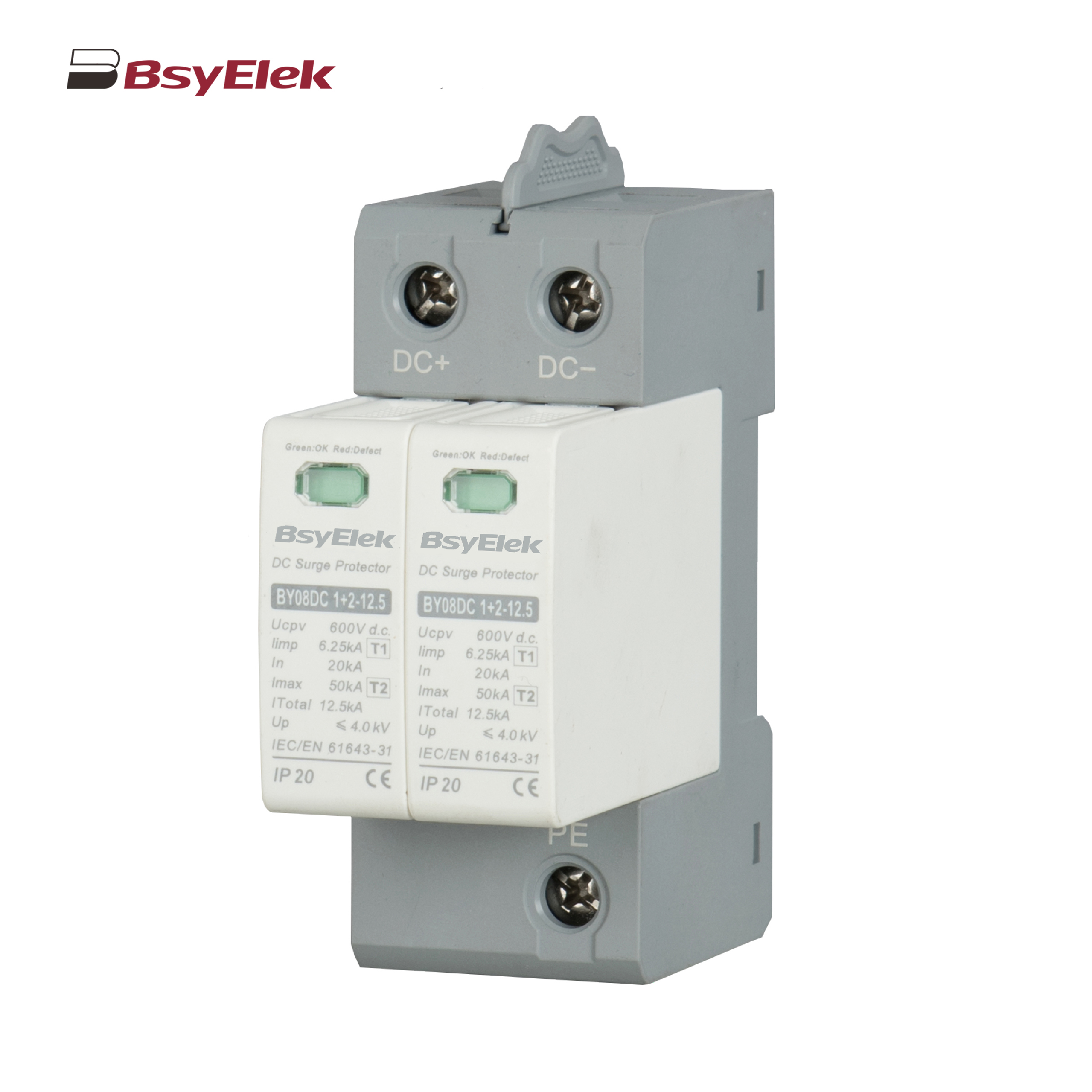
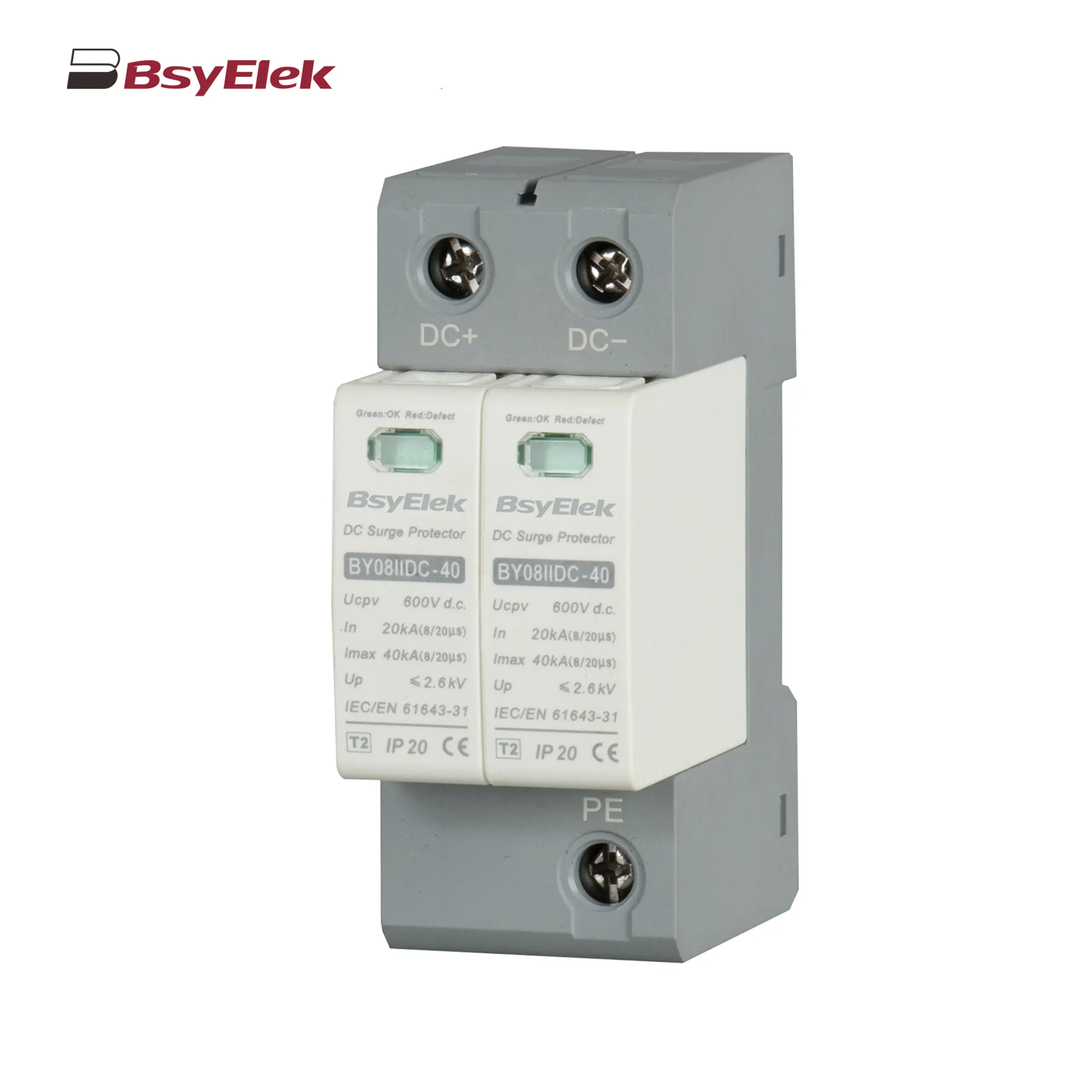
| Surge exposure and SPD type | Assess lightning exposure, the building’s lightning protection system, cable routing, and local installation rules. | A Type 2 DC SPD is commonly used for induced surges. Consider a Type 1+2 SPD where a lightning protection system or the installation risk assessment calls for lightning-current protection. Follow applicable standards, including IEC 61643-31 and local wiring rules. |
| Maximum PV system voltage (UCPV) | Calculate the array’s maximum open-circuit voltage at the lowest expected cell temperature, using the module temperature coefficient and string configuration. | Choose an SPD with a UCPV rating at least as high as the calculated maximum PV voltage, and ensure it is compatible with the inverter’s maximum DC input voltage. Common system classes include 600 V, 1,000 V, and 1,500 V DC; these are not interchangeable. |
| Discharge-current rating | Check the rating and waveform stated for each protection mode: In and Imax for Type 2, or Iimp for Type 1. | Type 2 products commonly specify In values in the 5–20 kA range and Imax values in the 20–40 kA range using an 8/20 μs waveform. Type 1 products specify Iimp using a 10/350 μs waveform. These are representative product ranges, not universal minimums; select ratings based on the risk assessment and project requirements. |
| Voltage protection level (Up) | Compare the SPD’s declared Up with the impulse withstand voltage of the inverter and other protected equipment. | Choose a protection level low enough for the equipment, with suitable coordination between SPDs where multiple protection stages are installed. Account for additional voltage caused by connecting-lead inductance. |
| PV circuit configuration and poles | Confirm whether the array is floating or grounded and check the SPD’s connection diagram for the positive, negative, and protective-earth conductors. | Use an SPD specifically designed for PV DC circuits and compatible with the system earthing arrangement. Do not assume an AC SPD or a DC SPD intended for another application is suitable. |
| Short-circuit coordination | Check the SPD’s PV short-circuit withstand rating (often stated as ISCPV) against the array’s prospective short-circuit current, and verify any required backup fuse or overcurrent device. | Follow the SPD manufacturer’s coordination instructions and the applicable electrical code. The backup device must have the specified DC voltage and interrupting ratings; do not select it from current rating alone. |
| Installation location and lead length | Consider the distance between the array, DC isolator, SPD, and inverter, as well as the routing of positive, negative, and earth conductors. | Install the SPD close to the equipment it protects and keep connections short, direct, and routed to minimize loop area. Follow the installation standard and product instructions for conductor length and connection method. |
| Environment and status indication | Check the rated operating temperature, enclosure protection, UV exposure, humidity, and whether remote status monitoring is required. | Use an enclosure suitable for the installation location. A visual status indicator and, where needed, a remote alarm contact make it easier to identify an SPD that has reached end of life. |
| Important limitation | An SPD limits transient overvoltage; it is not a substitute for correct wiring, bonding, grounding, or lightning protection. | It does not provide general protection against sustained overvoltage or every direct-lightning event. Have the system designed, installed, and inspected by a qualified professional. |
Ratings and selection requirements vary by system design, installation conditions, and local regulations. Verify calculations and product documentation before installation.
Start with the array’s maximum DC voltage, not the inverter’s AC rating. Add the module open-circuit voltages in each series string, then correct for the lowest expected site temperature. Cold weather raises module voltage. Check the cold case. NREL’s 2024 Annual Technology Baseline uses 1,500 V DC as a utility-scale PV design basis; that figure is not a default for every rooftop system. Confirm your actual maximum against module and inverter specifications.
Next, map the array layout. Series modules raise voltage; parallel strings raise current. Record the number of strings connected to each combiner or inverter input, then calculate the relevant short-circuit current using module data and applicable design factors. Do not treat an SPD’s discharge-current rating as the array’s operating current. Check its PV short-circuit current withstand rating and required backup protection. Small details matter. A neat string diagram can prevent a missed parallel path.
Choose an SPD with a maximum continuous operating voltage above the corrected array voltage, while keeping protection voltage compatible with the inverter’s withstand rating. IEC 61643-31:2018 covers surge protective devices for photovoltaic DC systems up to 1,500 V. Verify the device’s ratings against that standard and the installation instructions. One thing is easy to overlook: arrays with separated roof sections or long DC cable runs may need protection at more than one location. The layout matters as much as the nameplate.
A DC surge protective device must match the solar array’s wiring and exposure, not just its nominal voltage. Type 2 devices are commonly installed on the DC side to limit induced surges. Where a site has an external lightning protection system or greater direct-strike exposure, a Type 1 or combined Type 1+2 device may be specified. Check the system design and local requirements rather than guessing. Placement matters: long cable runs between panels and inverter can reduce protection. Keep connections short and follow the equipment instructions. Small details count.
Match the device’s maximum continuous operating voltage, Ucpv, to the array’s highest possible open-circuit voltage. Calculate that voltage using the module data and the lowest expected site temperature, because cold conditions raise Voc. Cold matters. The selected Ucpv must not be below the corrected array voltage. Also compare the protection level, Up, with the inverter’s impulse withstand rating; a lower Up generally offers tighter voltage limitation, when the devices are properly coordinated. Check discharge-current ratings and the device’s short-circuit current capability against the array’s available fault current.
Grounding arrangements affect which poles need protection, so confirm whether the array is floating or referenced to earth. Do not assume every system uses the same connection layout. I would verify the inverter manual, cable distances, and temperature calculation before choosing a model; it is easy to overlook one of them. A qualified solar electrician can confirm the final selection and installation.
Place a DC surge protective device near the inverter’s PV input, where it can help limit surges entering the equipment. The inverter end matters. If array cables run a long distance or pass between separate structures, consider protection near the array combiner as well. The right arrangement depends on cable length, system layout, and the device manufacturer’s coordination guidance; adding devices without checking compatibility can create confusion rather than better protection.
Match the protector to the array’s maximum possible DC voltage, including cold-weather conditions, and confirm its polarity and current ratings suit the circuit. Install it in parallel, following the wiring diagram, with conductors kept short and direct. A tidy enclosure is useful, but it does not compensate for a long, looping connection. That detail is easy to underestimate.
Bond the protector’s grounding terminal to the system’s equipotential bonding point using a short, appropriately sized conductor. Avoid sharp bends and unnecessary loops, which can increase the path’s impedance during a fast surge. Do not create an isolated grounding arrangement just for the protector. Check the equipment instructions and applicable electrical requirements, then inspect that connections are secure and accessible. Even a careful plan may need revision when the actual cable route differs from the drawing.
How to Choose a DC Surge Protector for Solar Panels
A DC surge protector should match the actual electrical conditions of your solar array, not just its advertised voltage. Check the system’s maximum open-circuit voltage, including the increase that can occur on cold mornings. The protector’s continuous operating voltage must suit that value. Confirm the polarity, current ratings, and whether the device is designed for photovoltaic DC circuits. Check the label first. Small details matter.
Safety standards deserve equal attention. Look for compliance with standards applicable to photovoltaic surge protection, such as IEC 61643-31 or its locally adopted equivalent. Requirements can vary by region, so verify the current rules with a qualified installer or electrical authority. A certification mark is useful, but it does not prove that the device fits your system. Also consider the installation’s lightning protection and grounding design; the right protector depends on both. A neat-looking specification sheet can still leave important questions unanswered.
Maintenance is easy to overlook. Choose a unit with a clear status indicator and accessible documentation. During routine system checks, look for a changed indicator, cracked housing, loose connections, or signs of moisture. After a severe storm, arrange an inspection rather than opening an energized enclosure yourself. Some protectors need replacement after absorbing a surge, even when the panels still produce power. That part is easy to miss. Keep a record of inspections and follow the manufacturer’s replacement guidance, though the schedule may need adjustment for local weather and system conditions.
Check the applicable safety standards, verify that the SPD’s maximum continuous operating voltage (UCPV) is suitable for the array’s maximum corrected open-circuit voltage, and plan regular inspections.
Standardized test waveforms: Type 1 uses a 10/350 µs current impulse; Type 2 uses an 8/20 µs current impulse. The chart compares their nominal time-to-half-value—not the protection level or service life of a specific SPD. For PV installations, check the relevant requirements, including IEC 61643-31, and follow local codes. Inspect status indicators and replace an SPD that has reached end of life.